
Parallel-flow two-stage condensation heat pump water heater

A heat pump water heater and condenser technology, which is applied in the field of heat pump water heaters and downstream two-stage condensing heat pump water heaters, can solve the problems that the amount of hot water cannot meet water requirements, application site restrictions, and high costs, and achieves the reduction of water resources and thermal energy. The effect of waste, simple structure and high heating efficiency

Active Publication Date: 2010-12-22
JIANGSU TENESUN ELECTRICAL APPLIANCE
View PDF8 Cites 7 Cited by
  • Summary
  • Abstract
  • Description
  • Claims
  • Application Information

AI Technical Summary

Problems solved by technology

However, there is also the fact that the amount of water in the water tanks at all levels is limited, and sometimes it cannot meet the requirements of using hot water in large quantities. For example, the water in solar water heaters in some hotels, restaurants, and schools is often concentrated at night. Only the amount of water in the solar water heaters cannot Provide water requirements for more people
At the same time, in the fine weather environment with long sunlight exposure time, the water in the solar water heaters at all levels is basically heated to a higher temperature, and some are pressed out from the water supply tank, resulting in waste of water resources and heat energy.
On the one hand, the amount of hot water cannot meet the water requirements, and on the other hand, part of the hot water is lost
Secondly, solar water heaters meet the needs of domestic water, and have not been applied as drinking water requirements.
[0004] At the same time, there are still some high-temperature hot water heat pump devices on the market, most of which are mainly dedicated compressors and mixed high-temperature working fluids, and the cost is relatively high.
There is also a cascading two-stage compression technology, which is limited in its application due to the high temperature on the heat source side.

Method used


Image

  • Parallel-flow two-stage condensation heat pump water heater
  • Parallel-flow two-stage condensation heat pump water heater

Examples


Embodiment

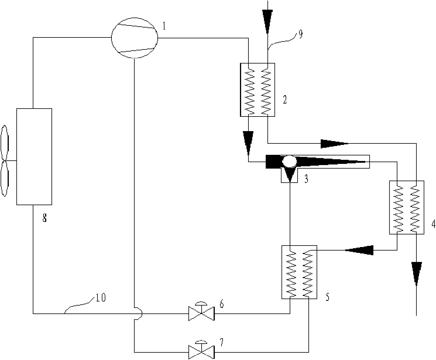
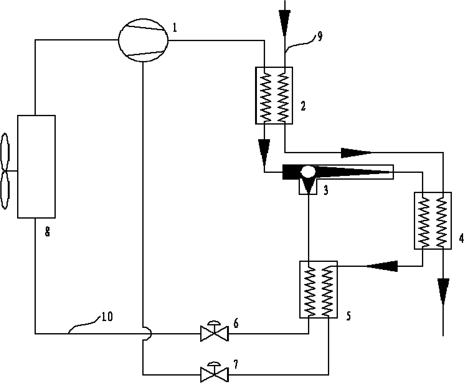
[0013] Such as figure 1 Shown is a schematic structural view of the downstream two-stage condensing heat pump water heater of the present invention. It includes a supplementary air enthalpy compressor 1, a primary condenser 2, a secondary condenser 4, a vortex tube refrigerator 3, an economizer 5, throttle valves 6, 7 and an evaporator 8; The exhaust port of the machine 1 is connected with the primary condenser 2, the air inlet of the vortex tube refrigerator 3, the low-temperature exhaust end of the vortex tube refrigerator 3, the economizer 5, the throttle valve 6, the evaporator 8 and the supplementary air enthalpy increase The suction port of the compressor 1 is connected in turn to form a fluorine side circulation flow path; the exhaust port of the air-supplementing enthalpy increasing compressor 1 is connected with the primary condenser 2, the intake end of the vortex tube refrigerator 3, and the vortex tube refrigerator The high-temperature exhaust end of 3, the econom...


PUM


Abstract

The invention relates to a parallel-flow two-stage condensation heat pump water heater comprising an air-supply enthalpy-rise compressor, a first-stage condenser, a second-stage condenser, a vortex tube refrigerator, an economizer and an evaporator; an exhaust port of the air-supply enthalpy-rise compressor is connected with the first-stage condenser, the air inlet end of the vortex tube refrigerator, the low-temperature exhaust end of the vortex tube refrigerator, the economizer, a throttling valve, the evaporator and an air entry of the air-supply enthalpy-rise compressor in sequence to form a fluorine collateral circulation flow path; and the first-stage condenser and the second-stage condenser are connected by a water pipe to form a water collateral circulation flow path. Under the driving of the water pump, the water flowing direction of the water collateral circulation flow path is same with the fluorine flow direction in the fluorine collateral circulation flow path, therefore, the heat exchange efficiency of water flow and fluorine flow is improved. The heat pump water heater adopts a conventional refrigerating fluid working medium, can heat water until boiling, has simple structure and high heating efficiency and reduces the wastes of water resources and heat energy.

Description

technical field [0001] The invention relates to the field of household electrical appliances, in particular to a heat pump water heater, in particular to a downstream two-stage condensing heat pump water heater. Background technique [0002] The outlet water temperature of the heat pump water heater is determined by the condensing temperature of the heat pump system. For the R22 system, the condensing temperature is 65°C, and the corresponding system pressure is 2.75MPa; for the R410a system, the condensing temperature is 65°C, and the corresponding system pressure is 4.15MPa. After removing the heat exchange temperature difference, the outlet water temperature of 60°C has become the limit outlet water for heat pump water heaters on the market. temperature. A water temperature of 60°C is sufficient for bathing water and other living areas, but in some industrial fields a higher temperature is required, generally 75-85°C or even higher water temperature is required. [0003...

Claims


Application Information

Patent Timeline
IPC IPC(8): F24H4/02
Inventor 王天舒丁亮王玉军孙永剑季忠海
Owner JIANGSU TENESUN ELECTRICAL APPLIANCE
Learn More