
Reciprocating type heat radiation air-preheating energy-saving fire grate

A technology of air preheating and heat radiation, applied in the field of grate, can solve the problems of large heat radiation loss, rising combustion temperature, easy corrosion and so on

Inactive Publication Date: 2010-11-24
梁银梅 +1
View PDF7 Cites 0 Cited by
  • Summary
  • Abstract
  • Description
  • Claims
  • Application Information

AI Technical Summary

Problems solved by technology

[0005] In order to overcome the traditional air preheater's complex structure, large space occupation, easy carbon deposition, easy corrosion, high operation and maintenance costs, and at the same time, in order to overcome the low combustion temperature of the fixed grate, and the mechanical grate is easy to burn out and has a short life , large heat radiation loss, serious coal fall, and the water-cooled mechanical grate occupies a large space, complex structure, many faults, serious coal fall, and limited combustion temperature rise. The invention provides a mechanical grate that can be used Stir to make the ash on the surface of the fuel fall off, increase the contact coefficient between the air and the fixed carbon, and convert the heat radiated from the bottom surface of the fuel to the grate into the physical heat of air heating, preheat the air, and return it to the furnace to participate in the combustion, thereby more effectively Improve the combustion efficiency and combustion temperature, reduce the temperature of the grate, increase the life of the grate, reduce the radiation heat loss on the bottom surface of the fuel and reduce the loss of falling coal. The reciprocating heat radiation air preheats the energy-saving grate

Method used


Image

  • Reciprocating type heat radiation air-preheating energy-saving fire grate
  • Reciprocating type heat radiation air-preheating energy-saving fire grate
  • Reciprocating type heat radiation air-preheating energy-saving fire grate

Examples


Embodiment 1

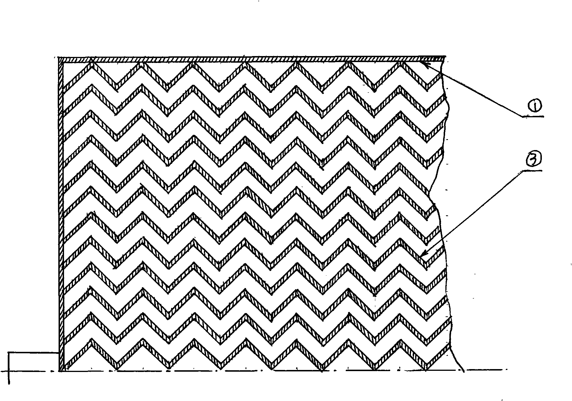
[0072] Example 1: In figure 1 In the square outer frame or frame 1, the corrugated slats 3 are erected equidistantly, and the support arms 2 are symmetrically installed outside the frame 1 to form a sub-grate; Figure 5 Among them, the support arm 2 on each sub-grate and the corresponding round hole 6 on the grate bracket 4 form a pair of rotary motion pairs, which can be partially rotated under the action of the push rod, so that the upper surface of the row bar can be used as a rotary motion. Reciprocating semi-arc movement, thereby stirring the fuel, several sub-grates form a grate.

Embodiment 2

[0073] Embodiment 2: The sub-grate structure remains unchanged. exist Figure 4 Among them, the round hole 6 on the grate support 4 is opened on the trapezoidal slider 7, and the grooves formed by the trapezoidal slider 7 and the vertical pair of trapezoidal retaining bars 5 form a pair of sliding kinematic pairs, and the slider 7 can be positioned at the top Under the action of the rod 8, it moves up and down. When the wedge 9 is pushed forward to the corresponding position, due to the action of the inclined plane of the wedge 9, the ejector rod 8 is pushed upward to the top dead center, so that the corresponding sub-grate rises to the top dead center, and the corresponding Due to the lack of support of the wedge 9, the adjacent sub-grate falls to the bottom dead center under the action of its own gravity or spring force. In this way, the adjacent sub-grate forms a certain height difference. At this time, the push rod pushes the lower position. The lower part of the sub-grat...


PUM


Abstract

The invention provides a reciprocating type heat radiation air-preheating energy-saving fire grate. The fire grate agitates the fuel by using mechanical movement of the fire grate to drop out clinkers on the fuel surface so as to increase the contact factor between air and fixed carbon; and simultaneously, air is preheated by convection heat transfer by using the heat radiated to a wavelike grate board of the fire grate from the bottom of the high-temperature fuel. Under the dual action of mechanical agitation and air preheating, the combustion efficiency and the combustion temperature are obviously increased, the temperature of the fire grate is lowered, the problems of easy burning loss and serious coal drop of the mechanical fire grate are solved, the energy efficiency of the boiler is increased by 15-20%, the boiler output is increased by 25-35%, the life of the fire grate is prolonged by 3-4 times, and the operation is stable and reliable.

Description

Technical field [0001] The invention relates to a fire grate, in particular, the mechanical movement of the fire grate can be used to stir the fuel to make the ash on the surface of the fuel fall off, and at the same time, the heat radiation from the bottom surface of the fuel can be used to preheat the air to improve the combustion efficiency and temperature. A fire grate that achieves the purpose of energy saving. Background technique [0002] The traditional air preheater uses the waste heat of the flue gas to preheat the air through a heat exchanger, and then transports it into the furnace to participate in combustion. This type of air preheater has a complex structure, takes up a lot of space, is easy to deposit carbon, is easy to corrode, and has high operation and maintenance costs. And when the preheated air enters the furnace through the grate, the temperature of the grate will rise, which will deteriorate the working environment of the grate and accelerate the oxi...

Claims


Application Information

Patent Timeline
IPC IPC(8): F23H11/00F23H11/20F23L15/00
CPCY02E20/34
Inventor 梁银梅李光
Owner 梁银梅
Learn More