
Low temperature smoke temperature difference generator

A technology of thermoelectric power generation and low-temperature flue gas, which is applied in the direction of generators/motors, electrical components, etc., can solve the problems of reducing the total efficiency of power generation, increasing energy consumption, and reducing power generation efficiency, so as to improve thermoelectric conversion efficiency, high-efficiency heat absorption and Effect of heat dissipation and saving cooling energy

Inactive Publication Date: 2010-11-10
王峰
View PDF8 Cites 16 Cited by
  • Summary
  • Abstract
  • Description
  • Claims
  • Application Information

AI Technical Summary

Problems solved by technology

The structure of the thermoelectric heat pipe of this patent is relatively complicated, which brings difficulties to manufacture
Second, its thermoelectric power generation sheet is directly in contact with the heat medium, which is easily polluted
Third, since the thermoelectric power generation sheet transfers heat through the heat-collecting insulation sleeve and the heat pipe, this also increases the heat transfer resistance, thereby reducing the power generation efficiency
Fourth, if a single heat pipe of the device fails, the heat from the thermoelectric sheet cannot be dissipated, which will cause the temperature difference between the two sides of the thermoelectric sheet to shrink, resulting in the burning of the semiconductor element
The semiconductor forced cooling fin structure of this patent requires additional energy consumption for water cooling or air cooling, which will not only complicate the system of the thermoelectric power generation device, but also easily cause leakage of the cooling medium, and greatly reduce the overall efficiency of power generation
[0007] However, the current thermoelectric power generation device technology needs to use a dedicated cooling system in order to maintain the temperature difference between the two ends of the semiconductor, which increases additional energy consumption and reduces the overall efficiency of power generation, so the application of thermoelectric power generation technology is subject to certain restrictions. limit

Method used

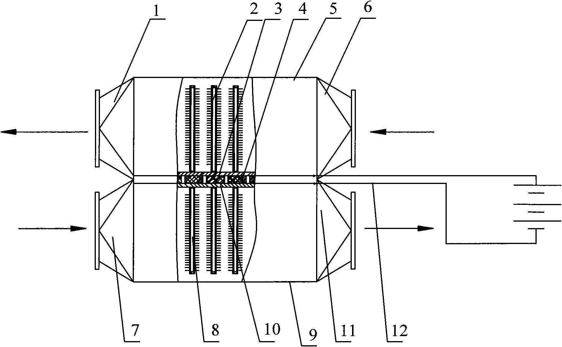
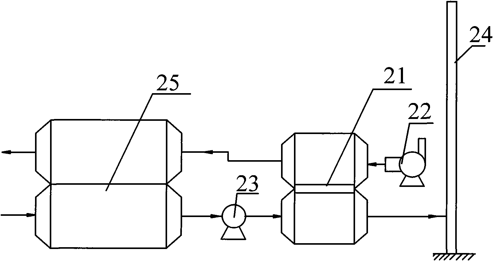

Image

  • Low temperature smoke temperature difference generator
  • Low temperature smoke temperature difference generator
  • Low temperature smoke temperature difference generator

Examples


Embodiment Construction

[0015] A preferred embodiment will be given below, and the present invention will be described more clearly and completely in conjunction with the accompanying drawings.

[0016] Thermoelectric power generation technology is a technology that uses the Seebeck effect (Seebeck Eiffct) of two connected conductors or semiconductors to convert heat energy into electrical energy. It is a circuit composed of two different types of semiconductors. When one end of the device is in a high temperature state and the other end is in a low temperature state, the formula for forming an electromotive force in the circuit is as follows:

[0017] ε=α s (T 2 -T 1 )................................................ ....................(1)

[0018] In formula (1): T1 is the temperature at the low temperature end, T2 is the temperature at the high temperature end, and αs is the Seebeck coefficient of the thermoelectric conversion material used. In application, multiple PN junctions are connected...


PUM


Abstract

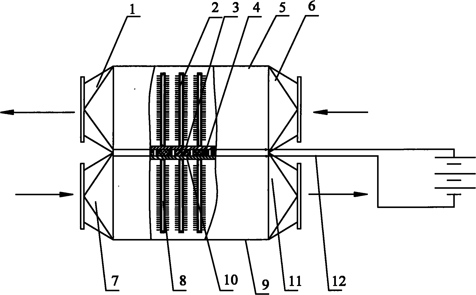
The invention discloses a low temperature smoke temperature difference generator which comprises an air outlet section, a normal temperature hot pipe, a heat radiating guide plate, a semiconductor temperature difference module, an air shell, an air inlet section, a smoke inlet section, a low temperature hot pipe, a smoke shell, a heat collecting guide plate, a smoke outlet section and a lead, wherein the heat radiating guide plate and the heat collecting guide plate are respectively positioned at two opposite sides of the semiconductor temperature difference module, the normal temperature hot pipe is positioned above the heat radiating guide plate, the air outlet section and the air inlet section are respectively positioned at two opposite sides of the air shell, the lower temperature hot pipe is positioned below the heat collecting guide plate, the smoke inlet section and the smoke outlet section are respectively positioned at two opposite sides of the smoke shell, and the semiconductor temperature difference module is connected with the lead. By using low grade smoke discharged by a heating furnace air preheater to a chimney, part of low grade smoke is directly converted into usable electric energy by the lower temperature smoke temperature difference generator.

Description

technical field [0001] The invention relates to a power generation device used in petrochemical and coal chemical heating furnaces, in particular to a low-temperature flue gas temperature difference power generation device. Background technique [0002] At present, in order to save energy, the petrochemical tubular heating furnace has widely used the air preheating system to reduce the exhaust gas temperature of the heating furnace. Calculated according to the average thermal efficiency of the heating furnace of 90%, the temperature of the flue gas discharged to the atmosphere is 160-180°C. At present, there is no better recovery method for these low-grade heat energy. Among them, there are two ways to further reduce the exhaust gas temperature. One way is to continue to preheat the air, which is limited by the economy. As the exhaust gas temperature decreases, the temperature difference at the end of the flue gas waste heat recovery system becomes smaller and smaller, the...

Claims


Application Information

Patent Timeline
IPC IPC(8): H02N11/00
Inventor 王峰
Owner 王峰
Learn More