Dc-dc converter circuit
A technology of DC-DC and conversion circuits, which is applied in the field of DC-DC conversion circuits, can solve problems such as the application of surge voltages to rectifier components, and achieve the effect of improving efficiency
- Summary
- Abstract
- Description
- Claims
- Application Information
AI Technical Summary
Problems solved by technology
Method used
Image
Examples
Embodiment Construction
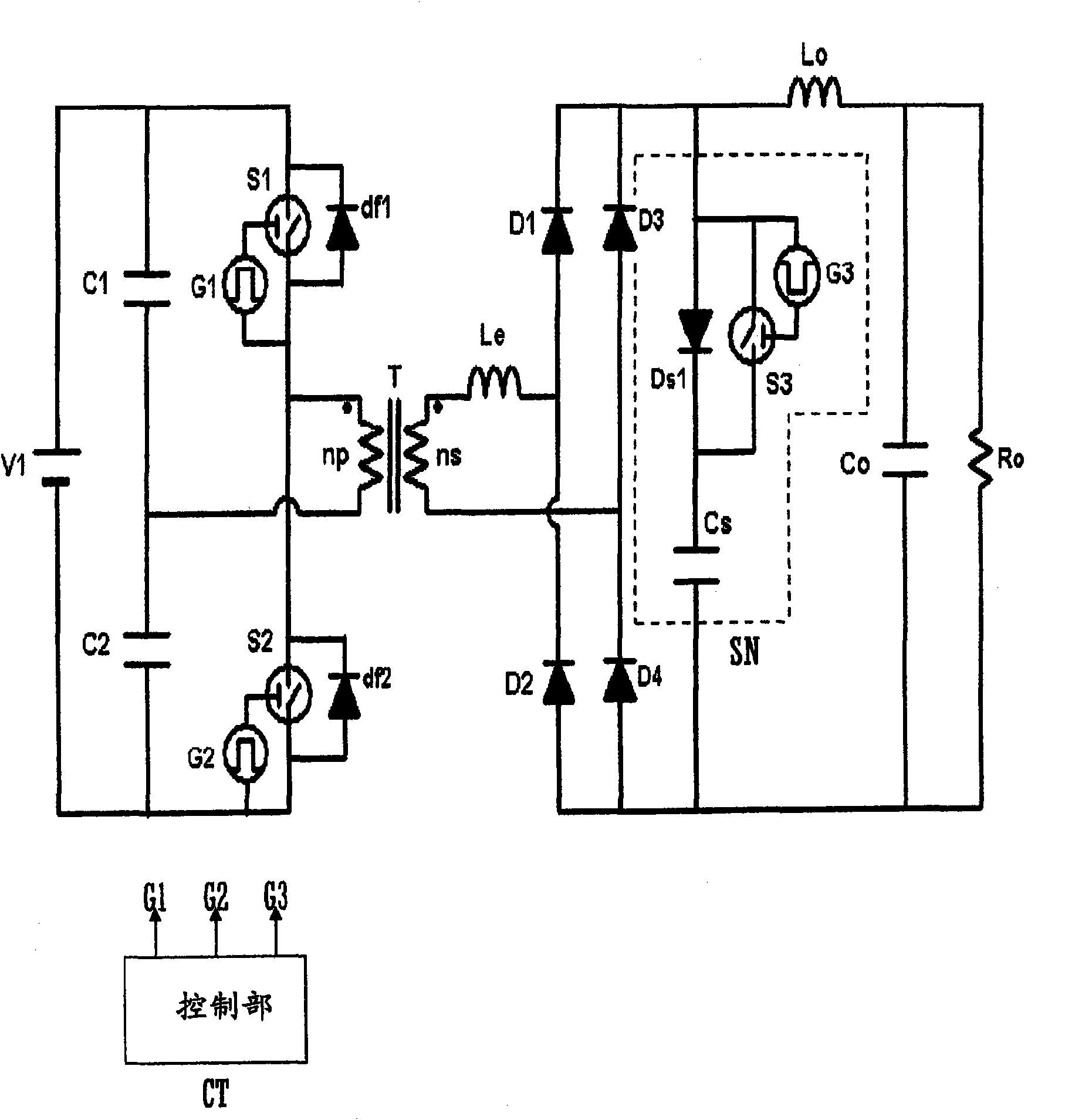
[0019] figure 1 It is a circuit diagram of a DC-DC conversion circuit according to an embodiment of the present invention.
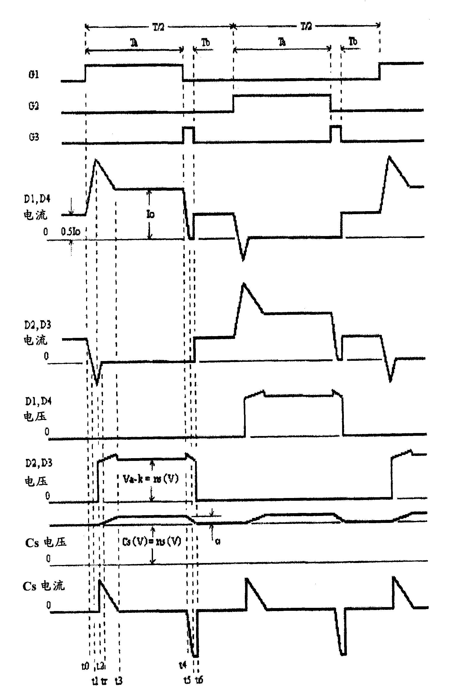
[0020] A series circuit of a first capacitor C1 and a second capacitor C2 serving as a voltage source is connected in parallel to the DC power supply V1, and primary-side switching elements, that is, a first switching element S1 and a second switching element S1, are respectively connected in parallel to the capacitors C1 and C2. Element S2. Each of the switching elements S1 and S2 is composed of a semiconductor switching element, for example, an IGBT (Insulated Gate Bipolar Transistor) or a MOS-FET. The primary coil np of the transformer T is connected between the connection point of the capacitors C1 and C2 and the connection point of the switching elements S1 and S2 . Freewheeling diodes (clamp diodes) df1 and df2 are connected in antiparallel to the switching elements S1 and S2, respectively. In addition, there is provided a control unit CT that o...
PUM
 Abstract
Description
Claims
Application Information
 - R&D
- Intellectual Property
- Life Sciences
- Materials
- Tech Scout
- Unparalleled Data Quality
- Higher Quality Content
- 60% Fewer Hallucinations
Browse by: Latest US Patents, China's latest patents, Technical Efficacy Thesaurus, Application Domain, Technology Topic, Popular Technical Reports.
© 2025 PatSnap. All rights reserved.Legal|Privacy policy|Modern Slavery Act Transparency Statement|Sitemap|About US| Contact US: help@patsnap.com


