Electroplating layer stress measurement device

A stress measurement and electroplating technology, applied in the direction of force measurement by measuring the change of magnetic properties of materials caused by applied stress, can solve the dispersion, sometimes zero, sometimes fluctuation, can not effectively eliminate the pointer drive wheel static friction, coating stress minor issues

Inactive Publication Date: 2011-08-24
邱安生
View PDF1 Cites 0 Cited by
  • Summary
  • Abstract
  • Description
  • Claims
  • Application Information

AI Technical Summary

Problems solved by technology

The reason for this shortcoming is mainly that at the initial stage of electroplating, the spiral spring shakes under the agitation of the air pump, and the pointer it drives swings, and the indication is unstable and inaccurate; at the same time, 10-15 minutes after the start of electroplating, due to the small , the deformation force of the spiral spring is small, which cannot effectively eliminate the influence of the static friction of the pointer drive wheel, so that the measured value of the instrument is scattered, sometimes it is zero, and sometimes the fluctuation is several times the steady state value. Generally, it takes 20 minutes to enter a relatively monotonous state. steady state process of change
[0007] The second disadvantage is the low sensitivity and large measurement error in the low stress range
Because the entire surface of the magnetic sensitive part of the sensor (including the hole wall of the magnetic circuit hole) is not insulated, a closed curved surface coating with complex interface shape and continuous shape is formed during electroplating. The stress composition is very complicated, and the type of stress cannot be determined. Whether it is tensile stress or compressive stress, the existing coating stress measurement method cannot be used for quantitative comparison and calibration, and it cannot be connected with the existing coating stress detection specifications
Therefore, it cannot be used for coating stress measurement that meets the testing standards.

Method used


Image

  • Electroplating layer stress measurement device
  • Electroplating layer stress measurement device
  • Electroplating layer stress measurement device

Examples


Embodiment Construction

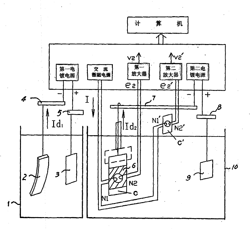
[0059] refer to figure 1 , The electroplating layer stress measuring device of the present invention is composed of an AC excitation power supply, a first electroplating power supply, a second electroplating power supply, a measuring sensor, a calibration sensor, a cathode sheet 2 and a computer. Among them, the frequency of the AC excitation power supply is 400 Hz, and the current is 200 mA, which remain unchanged during the measurement. The first electroplating power supply and the second electroplating power supply are pulse power supplies that can be modulated, and can also be converted into DC power supplies. Wherein the first electroplating power supply provides the electroplating current Id1 for the cathode sheet 2 and the corresponding anode plate 3, and the second electroplating power supply provides the electroplating current Id2 for the first magnetic sensitive sheet C of the measuring sensor and the corresponding anode plate 10, and Id1 and Id2 are measured deter...


PUM

PropertyMeasurementUnit
thicknessaaaaaaaaaa
diameteraaaaaaaaaa

Abstract

The invention relates to an electroplating layer stress measurement device, which consists of an AC excitation power source, an electroplating power source, a measurement sensor, a correction sensor, a cathode piece and a computer. The measurement sensor comprises a first magnetic sensing piece C forming a closed magnetic loop with a primary excitation winding N1 and a secondary sensing winding N2 wound thereon, and insulation paint being coated on the surface of the first magnetic sensing piece C except for a plane electroplating area. The correction sensor comprises a second magnetic sensing piece C' with the same structure, shape and magnetic property with the first magnetic sensing piece C, wherein the surface is sealed and insulated. The primary winding N1 and N1' of the two sensors are connected to the AC excitation power source after series connection, and the secondary winding N2 and N2' are respectively connected to a first amplifier and a second amplifier 2. The cathode piece is used for measuring the type of the stress. The electroplating layer stress measurement device has the advantages of short measurement period, high application measurement precision within the low-stress range and the like; and besides the type of the plating layer stress and the horizontal stress value, the device also can be used for measuring the connection force between the metal plating layer and the base body during the electric crystallization process.

Description

1. Technical field [0001] The invention relates to the measurement of force, especially a device for measuring the internal stress of electroplating layer. 2. Background technology [0002] As we all know, with the emergence of precision electroforming and micro-electroforming technology, many mechanical and mold parts with complex shapes and high precision requirements are made by electroforming. During the electroforming process, the casting coating will generate internal stress. Once the stress is too large, the casting will be deformed and scrapped, causing economic losses to production. The coating stress of castings is closely related to the process conditions of electroplating, and is affected by process parameters such as current density, temperature, metal ions in the bath and the content of various additives, and these parameters will continue to change during the electroforming process. During the casting process, samples are taken from the plating solution in th...

Claims


Application Information

Patent Timeline
Patent Type & Authority Patents(China)
IPC IPC(8): G01L1/12
Inventor 邱安生邱呈玉
Owner 邱安生
Why Eureka
Try Eureka