
Electroplated embossing plate and the manufacturing method of the same

A manufacturing method and embossing technology, applied in electroforming, electrolytic process, mechanical treatment of leather surface, etc., can solve the problems of low nickel weldability, high welding difficulty, rough abrasive adhesion surface, etc. separation effect

Inactive Publication Date: 2013-05-29
玄正淳
View PDF0 Cites 0 Cited by
  • Summary
  • Abstract
  • Description
  • Claims
  • Application Information

AI Technical Summary

Problems solved by technology

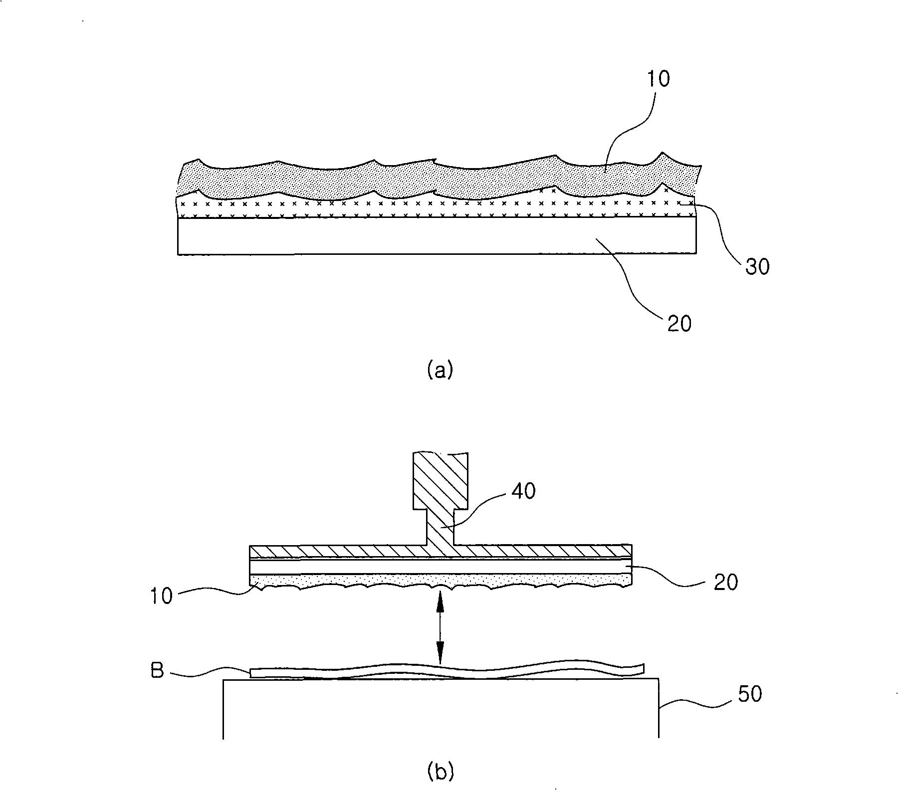
[0016] Therefore, in order to prevent the separation of the above-mentioned plated plate 10 and the support iron plate 20, the above-mentioned plated plate 10 is sometimes welded to the support iron plate 20. So welding is very difficult
Moreover, even if the above-mentioned plated plate 10 is welded to the supporting iron plate 20, there is a problem that the above-mentioned plated plate 10 and the supporting iron plate 20 are easily separated due to cracking of the welded portion as the stamping operation is performed for a long period of time.
[0017] As mentioned above, the existing nickel-plated embossing plate uses adhesives or welding to attach the nickel-plated plate to the supporting iron plate, but it is difficult to overcome the bad problem that the plated plate is separated from the supporting iron plate when it is used for a long time happened
Therefore, rough grinding of the adhesion surface has a certain effect on the copper-plated plate, but the adhesion strengthening effect of the roughening on the nickel-plated nickel plate is weak, and the above-mentioned bad problems cannot be solved.

Method used


Image

  • Electroplated embossing plate and the manufacturing method of the same
  • Electroplated embossing plate and the manufacturing method of the same
  • Electroplated embossing plate and the manufacturing method of the same

Examples


Embodiment Construction

[0052] Hereinafter, the electroplated embossed plate and its manufacturing method of the present invention will be described in detail with reference to the accompanying drawings.

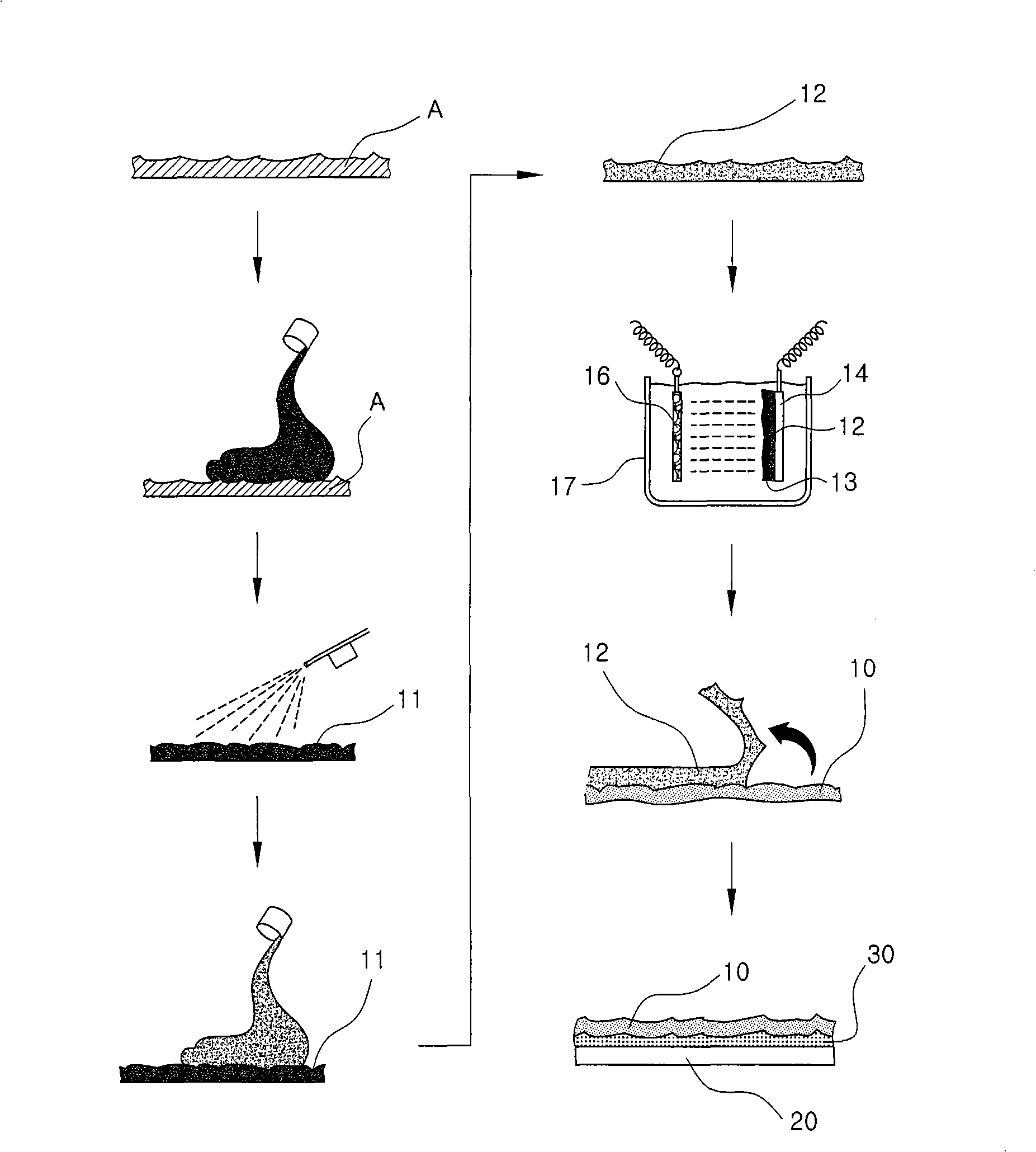
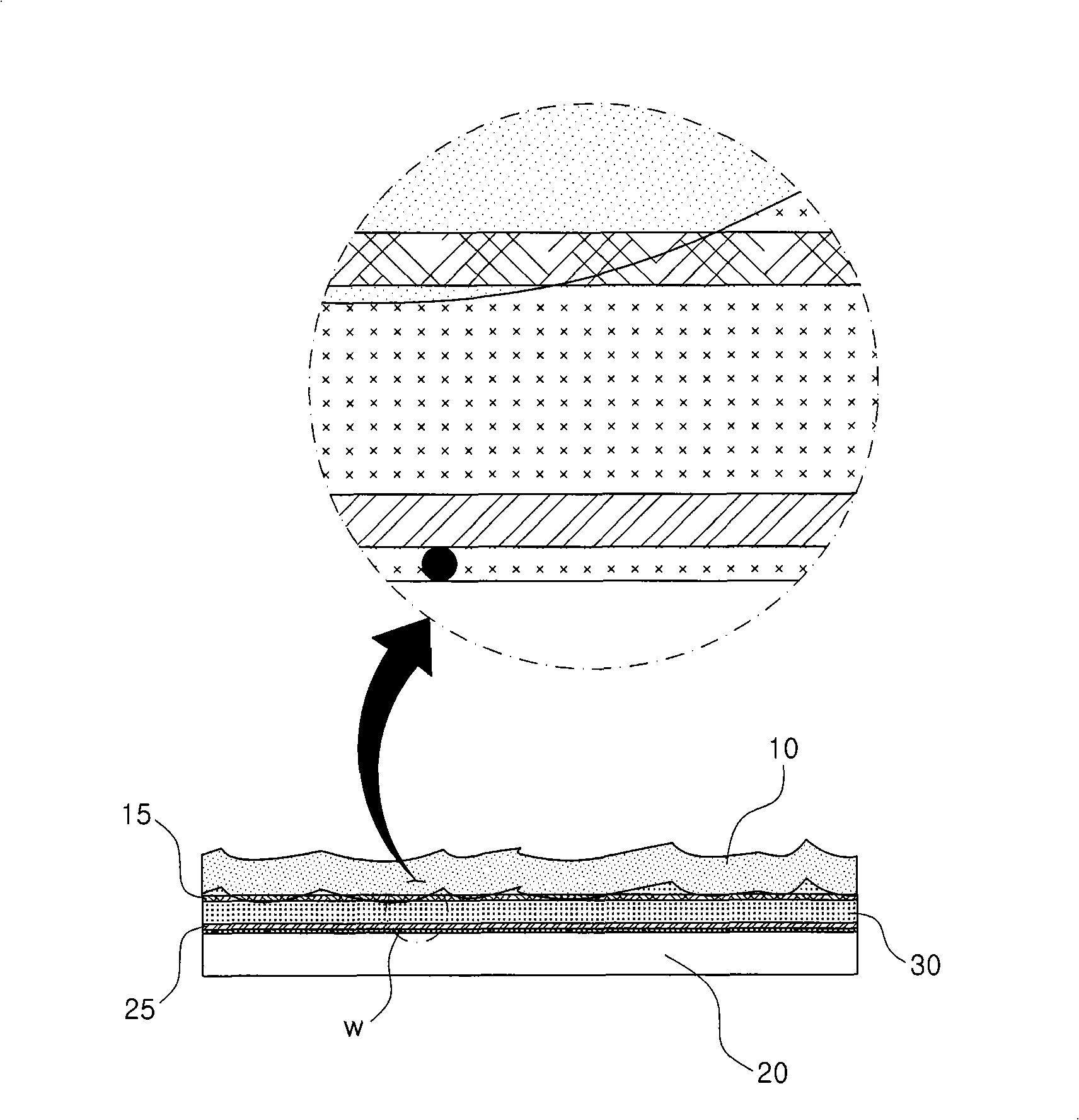
[0053] image 3 It is a structural diagram of the electroplating embossed version of the present invention, Figure 4 It is a flow chart of the manufacturing method of the electroplating embossed plate of the present invention, Figure 5 It is a reference drawing which shows the plating state of the plated plate which is the main part structure of this invention. in addition, Figure 6 It is a schematic process diagram showing the manufacturing process of a plated plate attached with a net-like structure as the main structure of the present invention, Figure 7 It is a structural diagram of a plated plate attached with a mesh structure as the main structure of the present invention, Figure 8 It is a reference drawing showing a supporting iron plate to which a metal net is attached as a main st...


PUM

PropertyMeasurementUnit
diameteraaaaaaaaaa

Abstract

The invention relates to an electroplated embossing plate and the manufacturing method of the same. The electroplated embossing plate comprises: a plating plate (10) capable of forming a leather master mask (A) pattern to be embossed by diaglyph; a mesh structure (15) adhered on the back of the plating plate (10) and forming a plating layer (13) thereon; a support iron plate (20) adhered on the back of the plating plate (10); a metal net (25) welded on the adhering surface of the support iron plate (20); and an adhesive layer (30) for adhering the plating plate (10) and the support iron plate(20) together after hardening the adhesive impregnated into the mesh structure (15) and the metal net (25). The manufacturing method corresponds with the structure of the electroplated embossing plate. Thus the adhesive is impregnated into the mesh structure integrated with the plating plate and the metal net welded with the support iron plate and then hardened, so as to integrate the adhesive layer, the mesh structure with the metal net; even thought the embossing plate is used for a long time, the plating plate is not separated from the support iron plate with increased endurance life.

Description

technical field [0001] The present invention relates to an embossing plate for transferring a specific pattern onto an object and a manufacturing method thereof, and particularly relates to improving the contact between a plated plate formed by plating nickel or copper onto a silicone resin plate and a supporting iron plate. Adhesive force, an electroplating embossing plate for preventing separation of a plated plate from a supporting iron plate during hot pressing operation, and a manufacturing method thereof. Background technique [0002] Usually, when processing natural leather or synthetic leather in a leather processing factory, it is used after using the inherent pattern of the original leather or embossing other patterns on the original leather. That is, a specific pattern is embossed on the raw leather with a plate or a roller having various patterns such as protrusions formed on the surface. For example, a crocodile pattern can be printed on a natural cowhide with ...

Claims


Application Information

Patent Timeline
Patent Type & Authority Patents(China)
IPC IPC(8): B23P15/24C14B1/56C25D1/00
CPCC25D5/34
Inventor 玄正淳
Owner 玄正淳
Learn More