
Air circulating system of integrated heat pump

A circulatory system, an integrated technology, applied in the field of air circulation systems, can solve the problems of high noise of fans, inability to purify air, and inability of air circulation systems to perform air purification and auxiliary cooling, and achieve the effect of improving utilization efficiency.

Inactive Publication Date: 2010-09-08
德华科电器科技(安徽)有限公司
View PDF4 Cites 4 Cited by
  • Summary
  • Abstract
  • Description
  • Claims
  • Application Information

AI Technical Summary

Problems solved by technology

The air source heat pump with split structure is composed of indoor unit and outdoor unit. The air circulation system and evaporator of the heat pump are installed in the outdoor unit. When the heat pump is working, the outdoor air is used to take away the cooling capacity during evaporation. The condensing fan of the heat pump directly blows the air cooled by the evaporator to the outside, and the air circulation system of the heat pump cannot perform air purification and auxiliary cooling
[0004] In the known air source heat pump with an integrated structure, the condensing fan all uses a high-power AC fan. This kind of fan has a lot of noise and blows out a high wind pressure, which is not conducive to human health. This kind of fan is not suitable for ventilation and replacement of the room. gas
Therefore, it is impossible to purify the air, and the evaporator cannot be used to cool the air.

Method used


Image

  • Air circulating system of integrated heat pump
  • Air circulating system of integrated heat pump
  • Air circulating system of integrated heat pump

Examples


Embodiment Construction

[0017] Below in conjunction with accompanying drawing for further detailed explanation,

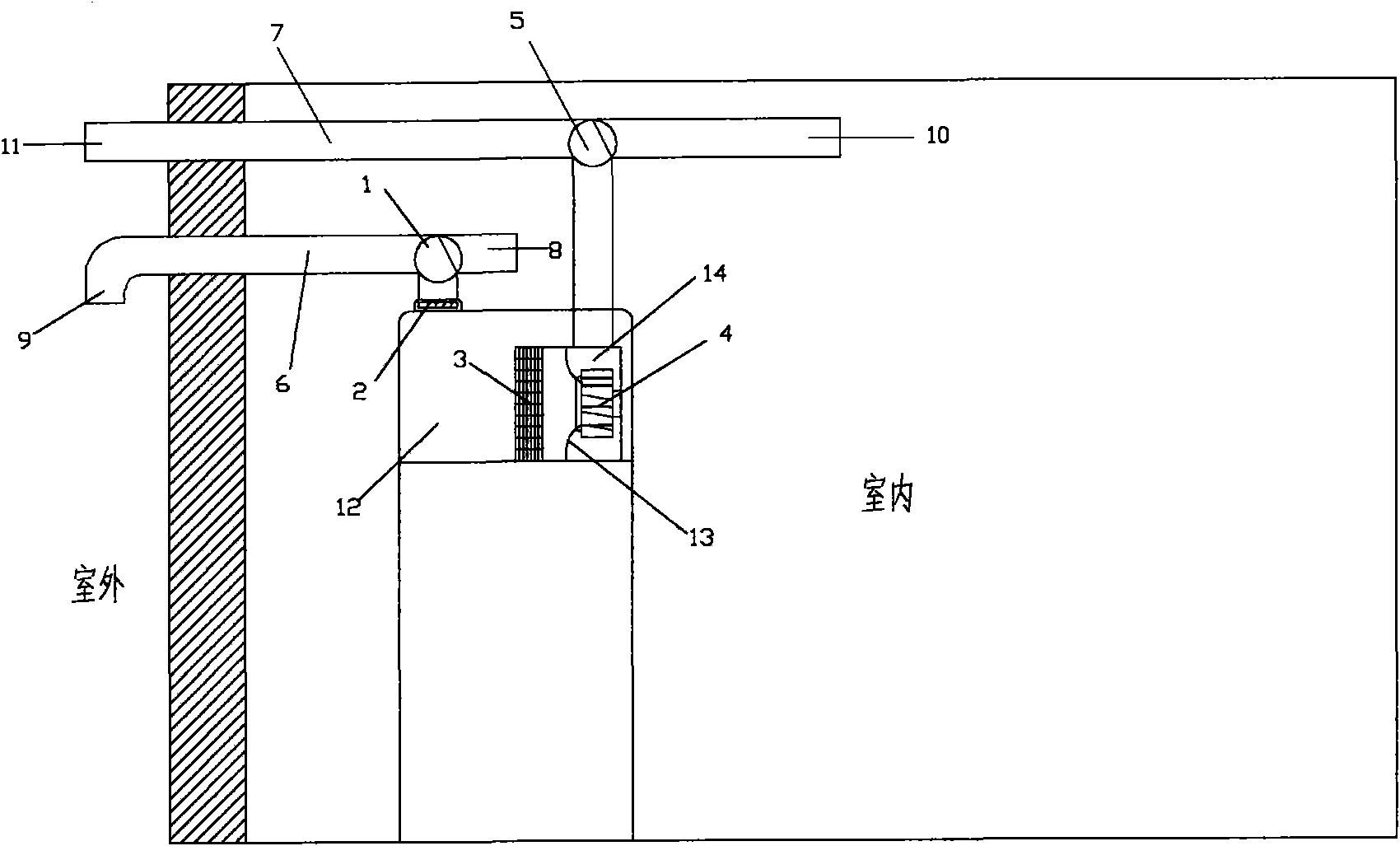
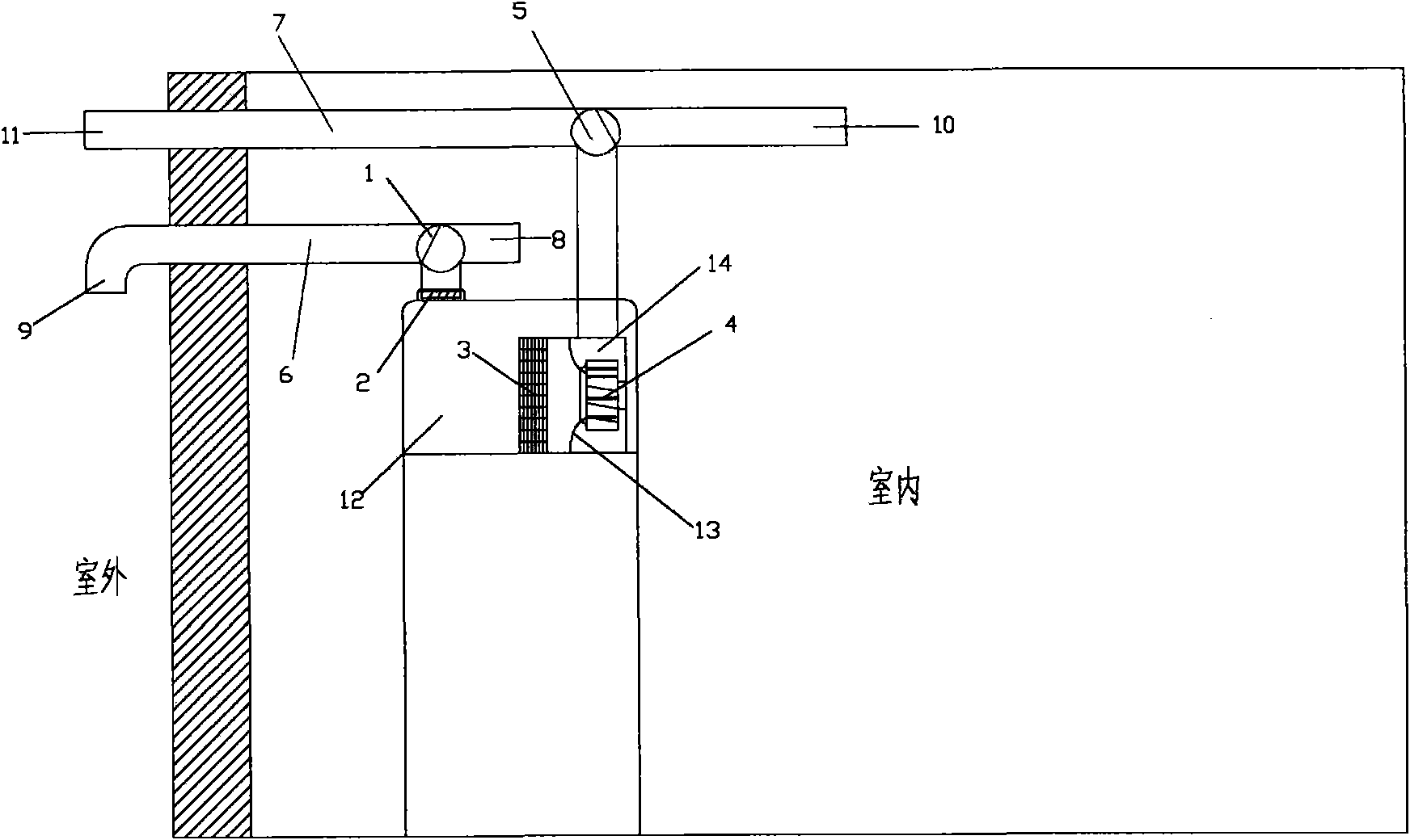
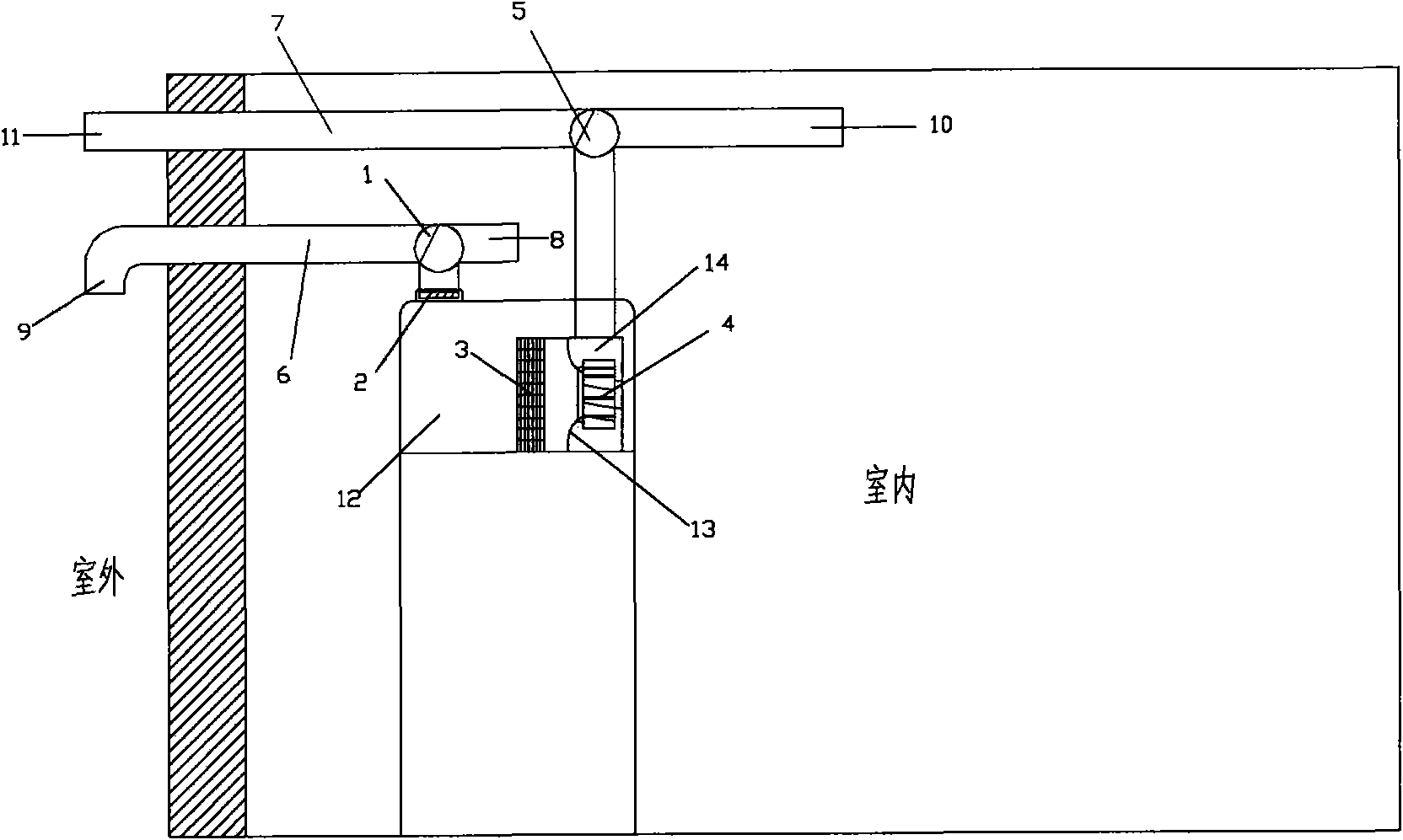
[0018] figure 1 The shown schematic diagram of the normal heating cycle of the present invention includes an air inlet 6, an outlet 7, a cooling fan 4 and a heat pump computer controller. The air inlet 6 is provided with an indoor air inlet 8 and an outdoor air inlet 9. An air inlet channel reversing mechanism 1 is set in the air inlet channel 6; an indoor air outlet 10 and an outdoor air outlet 11 are arranged on the air outlet channel 7, and an air outlet channel reversing mechanism 5 is arranged in the air outlet channel 7. The lower opening of the air inlet is connected to the heat exchange chamber 12 of the heat pump, and the lower opening of the air outlet is connected to the exhaust chamber 14 . The heat pump computer controller controls the action of the air inlet channel reversing mechanism 1, the air outlet channel reversing mechanism 5 and the cooling fan 4. An air cleaning d...


PUM


Abstract

The invention discloses an air circulating system of an integrated heat pump, which comprises an air inlet flue, an air outlet flue, a radiating fan and a heat pump computer controller, wherein the air inlet flue is provided with an indoor air inlet and an outdoor air inlet, and an air inlet flue reversing mechanism is arranged in the air inlet flue; and the air outlet flue is provided with an indoor air outlet and an outdoor air outlet, an air outlet flue reversing mechanism is arranged in the air outlet flue, a lower port of the air inlet flue is connected with a heat exchange cavity of the heat pump, and a lower port of the air outlet flue is connected with an exhaust cavity. The heat pump computer controller controls the operation of the air inlet flue reversing mechanism, the air outlet flue reversing mechanism and the radiating fan which also can be manually revered. An air purification device is arranged in a joint of the lower port of the air inlet flue and the heat exchange cavity of the heat pump. The air circulating system of the integrated heat pump can realize the functions of ventilation, air purification and auxiliary cooling, and also can improve the utilization efficiency of heat pump energy.

Description

technical field [0001] The invention relates to an integrated heat pump, in particular to an air circulation system of the integrated heat pump. Background technique [0002] "Heat pump" is a device that can obtain low-grade heat energy from air, water or soil in nature, and provide high-grade heat energy that can be used by people through electricity. When the heat pump is working, it consumes a part of the energy itself, excavates the energy stored in the environmental medium, and uses it by increasing the temperature through the heat transfer working medium circulation system, and the work consumed by the entire heat pump device is only a small part of the output work. , Therefore, the use of heat pump technology can save a lot of high-grade energy. Its working principle is the same as that of the air conditioner, and they all work according to the principle of "reverse Carnot cycle". [0003] At present, most known air source heat pumps adopt a split structure, and a f...

Claims


Application Information

Patent Timeline
IPC IPC(8): F24F1/00F24F7/06F24F13/28
Inventor 周小平张华庆孙勇
Owner 德华科电器科技(安徽)有限公司
Learn More