
Tungsten carbide welding rod and welding wire

A technology of tungsten carbide and tungsten carbide powder, which is applied in the direction of welding medium, welding equipment, welding/cutting medium/material, etc., can solve the problem of damaging the bonding strength of tungsten carbide and the base metal to be surfacing, and unfavorable wear resistance of the wear-resistant layer , tungsten carbide wear-resistant particles melting loss and other problems, to achieve significant economic and social benefits, convenient operation, and reduce the effect of shedding

Inactive Publication Date: 2010-08-25
朱明生
View PDF9 Cites 17 Cited by
  • Summary
  • Abstract
  • Description
  • Claims
  • Application Information

AI Technical Summary

Problems solved by technology

However, iron-based alloys and nickel-based alloys have relatively high melting points, that is, the surfacing temperature of these two materials is relatively high, and it is easy to cause melting damage to tungsten carbide wear-resistant particles, especially the former, which will cause casting tungsten carbide powder Decomposition, which is not conducive to the wear resistance of the wear-resistant layer, and damages the bonding strength between tungsten carbide and the base metal to be welded

Method used


Image

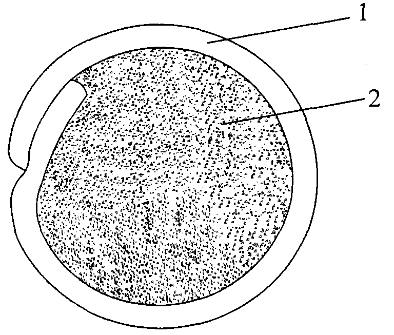
  • Tungsten carbide welding rod and welding wire
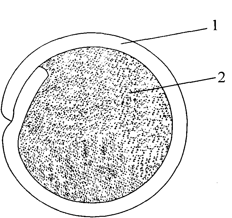
  • Tungsten carbide welding rod and welding wire

Examples


Embodiment 1

[0034] The skin is made of narrow-band zinc white copper (national standard brand BZn15-20, the content of Ni+Co varies between 13.5-16.5%, the content of Cu is 62-65%, the rest is mainly Zn, and the impurity content is below 0.9%) , through processing to form a tube with a diameter of 6 mm, wherein the outer skin accounts for 39% of the total weight of the electrode, and cast tungsten carbide powder (made by Beijing Dewang Machinery Electric Co., Ltd., WC-W2C, 20-30 mesh) accounts for 61% of the total weight . The product of this embodiment is subjected to an abrasive wear test, and the abrasive wear test is carried out with a dry-type rubber wheel wear tester manufactured according to the ASTM-G6-91 standard. The size after surfacing is 25mm×40mm×3mm. The test load is 13N, the abrasive is No. 120 brown corundum sand, the speed of the rubber wheel is 50r / min, the sand flow rate is 100g / min, and the wear time is 15min. The wear of the coating is expressed by weight loss, and ...

Embodiment 2

[0036] Red copper (national standard grade T2) is used as the outer skin, and 60% of the total weight is wrapped with cast tungsten carbide powder (manufactured by Beijing Dewang Machinery Electric Co., Ltd., WC-W2C, 48-65 mesh), and 5% Ni is also added. , 2% of Co, 1% of P, 1% of Si, 0.3% of Sn, 0.5% of Fe, 0.3% of Al and 0.5% of Mn alloy element powder, and then rolled, and finally drawn with a diameter of 2.8 mm filamentous. Using the same method as in Example 1, this example was subjected to an abrasive wear test. As a result, the weight loss of the overlay welding layer of the welding wire was 23 mg. The on-site comparison experiment on the roller cone bit also shows obvious advantages, and the operation is very convenient.


PUM

PropertyMeasurementUnit
diameteraaaaaaaaaa
diameteraaaaaaaaaa

Abstract

The invention provides a tungsten carbide welding rod and a tungsten carbide welding wire, which comprise a strip-shaped or filate tubular sheath and filler which is filled in the tubular sheath and comprises tungsten carbide powder. The tubular sheath contains over 50 percent of copper element; a welding temperature of the copper tungsten carbide welding rod or the welding wire is lower, so that the tungsten carbide is effectively prevented from being decomposed while overlaying, and wear-resisting property of the tungsten carbide is kept; the tubular sheath contains the copper, and the tungsten carbide is easy to wet, so that the bonding strength of the tungsten carbide and an overlaid base metal is effectively improved, the possibility that the tungsten carbide is fallen off is reduced when an overlaying part is under a using condition, and a wear-resistant part is prevented from becoming invalid; and the tungsten carbide welding rod and the tungsten carbide welding wire are widely applied to overlaying of a wear-resistant surface, particularly on-site remediation.

Description

technical field [0001] The invention relates to a surfacing welding material, in particular to a tungsten carbide electrode and welding wire, which are used as wear-resistant hard surface surfacing products, mainly used for tooth surface strengthening of steel teeth of roller cone bits, and can also be used for surface strengthening of other steel parts . Background technique [0002] In order to improve the surface properties of steel tooth roller cone bits or other steel parts often used in petroleum, mining, construction and other fields, thereby improving their service performance and life, tungsten carbide tubular electrodes are used as wear-resistant hard surface surfacing supplies And welding wire is widely used in their surface strengthening. [0003] At present, tungsten carbide electrodes and wires are used as wear-resistant hard surface surfacing supplies for the surfacing of steel tooth gear bits. There are two main types of materials: one is wear-resistant comp...

Claims


Application Information

Patent Timeline
Patent Type & Authority Applications(China)
IPC IPC(8): B23K35/30B23K35/368
Inventor 朱明生
Owner 朱明生
Learn More