One-dimensional membrane cavity structure-based different-bandwidth optical interleaver
A filter and film cavity technology, applied in optics, instruments, optical components, etc., can solve the problems of low yield and many layers of evaporated film, and achieve the effects of low production cost, flat filter characteristics, and high reliability
- Summary
- Abstract
- Description
- Claims
- Application Information
AI Technical Summary
Problems solved by technology
Method used
Image
Examples
Embodiment 1
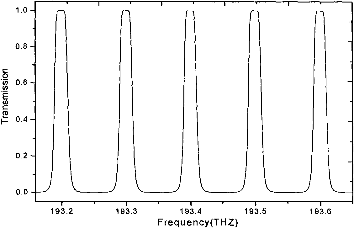
[0027] Embodiment 1: as figure 1 As shown, when the optical interleave filter of the present invention has a frequency interval of 100 GHz and a duty ratio of 1:5, the light beam passes through the collimating lens 2, 11 optical medium layers 3, and the focusing lens sequentially from the input optical fiber 1 along the direction in which the light beam advances. 4. Output from the output optical fiber 5. The materials A, B, C, and D of each dielectric layer of the filter are respectively selected as magnesium fluoride, zinc sulfide, glass, and lead antimonide, and the refractive indices are 1.38, 2.35, 1.51, and 4.1, respectively. The optical thicknesses of media A, B and D are all 387.53 nm, and the optical thickness of media C is 1498.97 μm. Transmission spectrum such as figure 2 shown. It can be seen from the figure that both the passband and stopband of the filter have flat filtering characteristics, and each center frequency conforms to the ITU-T standard of the Inte...
Embodiment 2
[0029] Embodiment 2: as figure 1 As shown, when the optical interleave filter of the present invention has a frequency interval of 100 GHz and a duty ratio of 1:3 and 1:4, the light beam passes through the collimating lens 2 and the 11-layer optical medium successively from the input optical fiber 1 along the direction of the light beam advance. Layer 3, focusing lens 4, output from output optical fiber 5. When the refractive indices of the medium layers A, B, C and D of the filter are 1.45, 1.99, 1.56 and 3.23 respectively, a spectral transmittance spectrum with a duty ratio of 1:3 is obtained. When the refractive indices of the dielectric layers A, B, C and D are 1.45, 2.35, 1.57 and 4.1 respectively, a spectral transmittance spectrum with a duty ratio of 1:4 is obtained. The optical thicknesses of media A, B and D are all 387.53 nm, and the optical thickness of media C is 1498.97 μm. Transmission spectrum such as Figure 4 shown. It can be seen that the pass-stop band cha...
PUM
| Property | Measurement | Unit |
|---|---|---|
| Optical thickness | aaaaa | aaaaa |
| Optical thickness | aaaaa | aaaaa |
Abstract
Description
Claims
Application Information
 - R&D
- Intellectual Property
- Life Sciences
- Materials
- Tech Scout
- Unparalleled Data Quality
- Higher Quality Content
- 60% Fewer Hallucinations
Browse by: Latest US Patents, China's latest patents, Technical Efficacy Thesaurus, Application Domain, Technology Topic, Popular Technical Reports.
© 2025 PatSnap. All rights reserved.Legal|Privacy policy|Modern Slavery Act Transparency Statement|Sitemap|About US| Contact US: help@patsnap.com


