
Special machine tool and method for boring double-support hole of spinning spindle elastic pipe combining member

A technology of special machine tools and joints, used in boring/drilling, drilling/drilling equipment, metal processing equipment, etc., can solve problems such as adverse effects on spinning output and quality, improve work stability, ensure Concentricity, the effect of improving machining accuracy

Inactive Publication Date: 2010-08-18
DONGHUA UNIV
View PDF0 Cites 7 Cited by
  • Summary
  • Abstract
  • Description
  • Claims
  • Application Information

AI Technical Summary

Problems solved by technology

When the spindle rod is inserted into the ingot liner to run, the part of the spindle rod immersed in lubricating oil in the elastic tube and the tapered hole at the bottom of the spindle is similar to the journal of the high-speed rotation of the sliding bearing, and the deviation of the journal from the center of the bearing will cause The oil film between the spindle rod and the elastic tube or the cone hole at the bottom of the spindle produces oil shock, which becomes an important factor to stimulate the self-excited vibration of the spindle, all of which will have a great adverse effect on the spinning output and quality

Method used


Image

  • Special machine tool and method for boring double-support hole of spinning spindle elastic pipe combining member
  • Special machine tool and method for boring double-support hole of spinning spindle elastic pipe combining member
  • Special machine tool and method for boring double-support hole of spinning spindle elastic pipe combining member

Examples


Embodiment Construction

[0027] Below in conjunction with specific embodiment, further illustrate the present invention. It should be understood that these examples are only used to illustrate the present invention and are not intended to limit the scope of the present invention. In addition, it should be understood that after reading the teachings of the present invention, those skilled in the art can make various changes or modifications to the present invention, and these equivalent forms also fall within the scope defined by the appended claims of the present application.

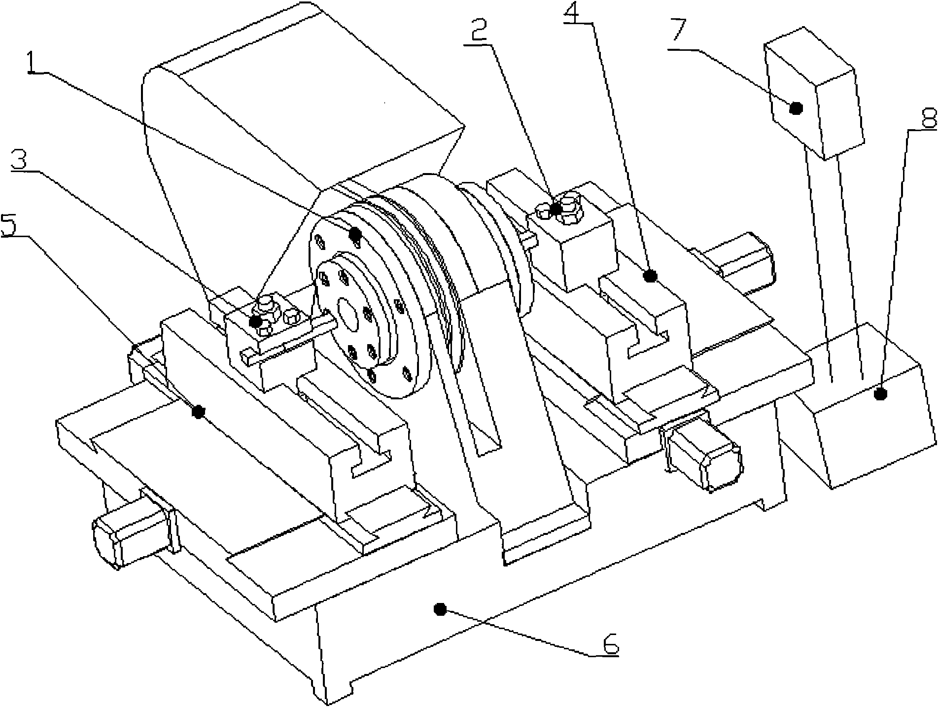
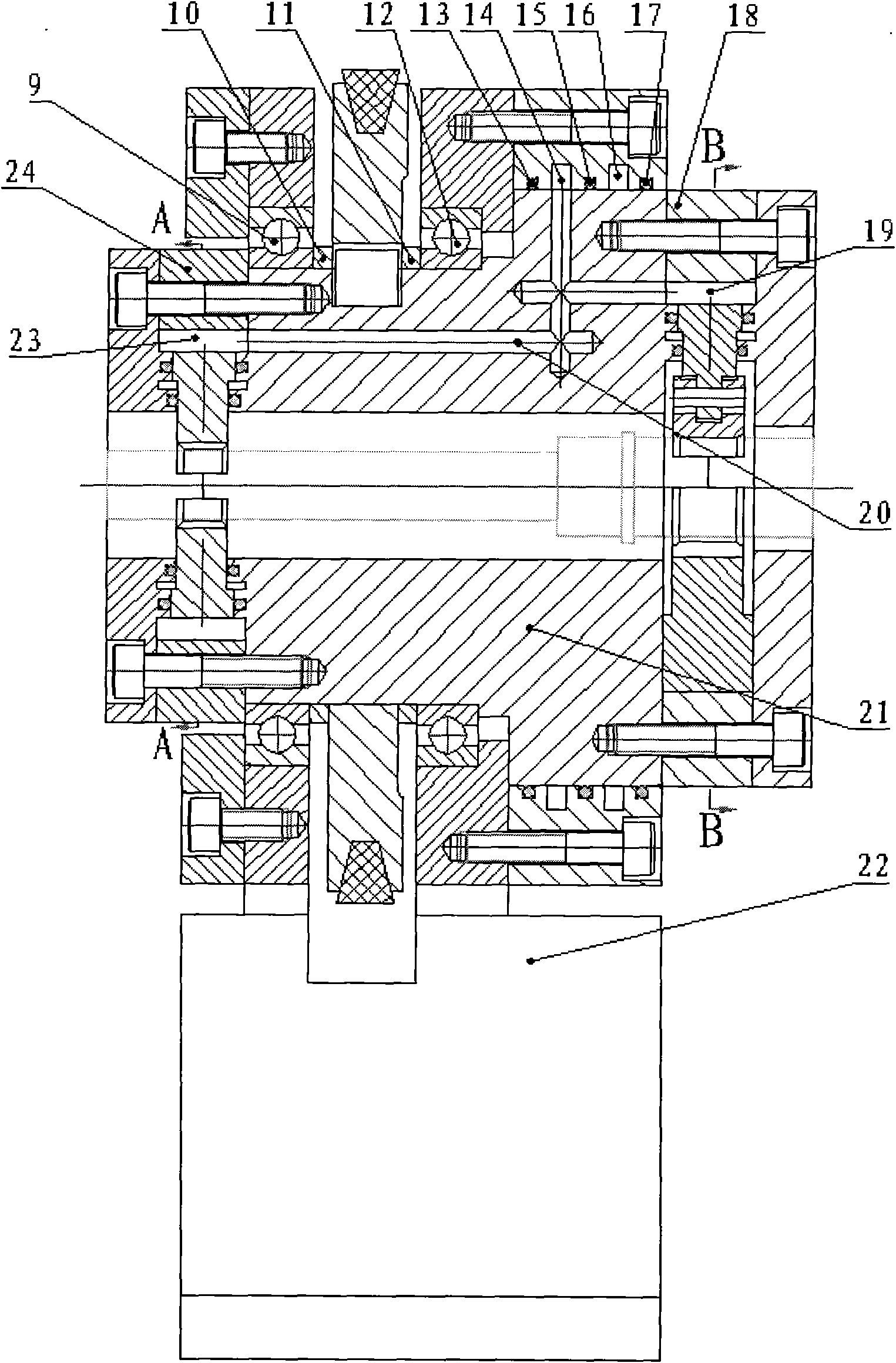
[0028] The embodiment of the present invention relates to a special machine tool for boring double support holes of the elastic tube joint of the spinning spindle, such as figure 1 As shown, it includes a spindle system 1, a left row tool rest device 3, a right row tool rest device 2, a bed 6, an operation panel 7 and an electrical control cabinet 8, and the spindle system 1 is installed on the bed 6 Right in the center; the b...


PUM


Abstract

The invention relates to a special machine tool and a method for boring a double-support hole of a spinning spindle elastic pipe combining member. The special machine tool comprises a main shaft system, a left knife rest distributing device, a right knife rest distributing device, a machine tool body, an operating panel and an electric control cabinet, wherein the main shaft system is installed in the very center of the machine tool body; a left vertical and horizontal sliding table device and a right vertical and horizontal sliding table device at the left side and the right side of the main shaft system are installed on the machine tool body; the left knife rest distributing device is installed on the left vertical and horizontal sliding table device, and the right knife rest distributing device is installed on the right vertical and horizontal sliding table device; the electric control cabinet is used for controlling the running of the special machine tool; and the operating panel is connected with the electric control cabinet. By using the excircle with larger diameter of the elastic pipe combining member as a positioning reference, after the special machine tool is self-adaptively positioned and clamped by a special camp, the precise boring of a double-support hole is simultaneously finished, the processing precision is improved, and the precision requirement for concentricity of the double-support hole of the high-speed spinning spindle elastic pipe combining member is ensured, thereby achieving the aim of improving the processing quality of yarn.

Description

technical field [0001] The invention relates to the field of precision manufacturing of textile machinery, in particular to a boring machine tool and method for double supporting holes of elastic tube joints of spinning spindles. Background technique [0002] my country's textile machinery and equipment technology lags far behind foreign industrialized countries, and many key equipment for medium and high-end textile fiber processing rely on imports. At present, most of the textile fiber processing equipment used by enterprises in my country comes from domestic manufacturing enterprises. Low quality and many quality problems have seriously affected the quality of textiles and the international competitiveness of high-end products. Spinning spindle is the foundation and core component of textile machinery equipment, one of the key elements affecting spinning quality and output, and plays a pivotal role in the development of the textile industry. The spindle amplitude is an im...

Claims


Application Information

Patent Timeline
Patent Type & Authority Applications(China)
IPC IPC(8): B23B41/00
Inventor 李蓓智刘向东向樟松王庆霞江小辉
Owner DONGHUA UNIV
Learn More