Device and method for replacing a vehicle battery pack
A technology for battery packs and vehicles, which is applied in electric power units, vehicle maintenance, power units, etc., can solve the problems of complex and bulky battery pack replacement equipment, high cost, etc., and achieve improved safety and stability, light transportation, and easy operation Effect
- Summary
- Abstract
- Description
- Claims
- Application Information
AI Technical Summary
Problems solved by technology
Method used
Image
Examples
Embodiment 1
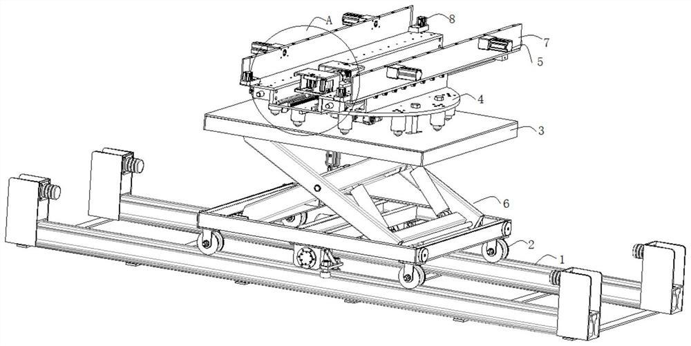
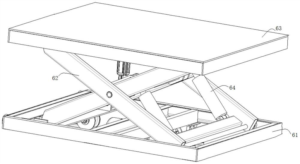
[0038]In this application, especially for the replacement of battery packs in new energy heavy trucks, because the battery packs on heavy trucks weigh about three tons, the existing battery pack replacement equipment is relatively cumbersome, and the light and flexible transportation of battery packs cannot be realized, and the cost is relatively high. high. Therefore if figure 1 , figure 2 with image 3 As shown, a device for replacing a vehicle battery pack is proposed, which specifically includes an underframe 1 on which a track for the lifting mechanism 6 to move on the underframe 1 is provided. Send the exhausted battery pack to the charging platform, and then send the fully charged battery pack in the charging platform to the vehicle. Therefore, a track is provided on the underframe 1, and the lifting mechanism 6 is connected with the wheels 2 to realize the running of the lifting mechanism 6 on the track, so that the lifting mechanism 6 arrives at a designated posit...
Embodiment 2
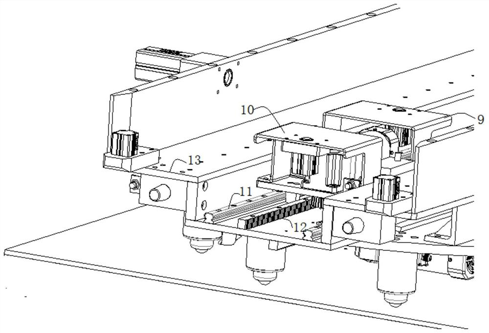
[0048] Basically the same as in Embodiment 1. Generally speaking, the vehicle that needs to replace the battery pack drives to the attachment of the charging platform, and is set face to face with the charging platform. In this implementation, the vehicle battery pack replacement device is set between the vehicle and the charging platform. The smooth performance of the package delivery, the drag mechanism in the vehicle battery pack replacement device specifically includes a push handle 9 and a handle 10 that are arranged oppositely, the push handle 9 is used to push the battery pack from the rolling plate 13 to the charging platform, and the handle 10 is used for Pull the battery pack from the bottom plate of the battery pack onto the rolling plate 13. A driving part is arranged between the push handle 9 and the handle 10, and the push-pull handles are connected with the driving part, and the driving part provides power for the push handle 9 or the handle 10 respectively, and ...
Embodiment 3
[0052] Basically the same as in Embodiment 2, in order to ensure that the battery pack is not disturbed by the external environment during the transportation process, in this implementation, limit plates 7 are provided on both sides of the rolling plate 13, and the limit plates 7 and the rolling plate 13 are vertically arranged . The setting of the limit plate 7 makes the transportation of the battery pack on the rolling plate 13 more stable, avoiding the situation that the battery pack shakes or is not firmly connected with the pulling mechanism and falls to the outside of the rolling plate 13, thereby improving the service life of the battery pack. Furthermore, when the battery pack needs to move from the rolling plate 13 to the charging platform, the entire device needs to be moved to the vicinity of the charging platform. At this time, the battery pack does not need to continue to slide on the rolling plate 13. The stability on the plate 13 is provided with a limit lock me...
PUM
 Abstract
Description
Claims
Application Information
 - R&D
- Intellectual Property
- Life Sciences
- Materials
- Tech Scout
- Unparalleled Data Quality
- Higher Quality Content
- 60% Fewer Hallucinations
Browse by: Latest US Patents, China's latest patents, Technical Efficacy Thesaurus, Application Domain, Technology Topic, Popular Technical Reports.
© 2025 PatSnap. All rights reserved.Legal|Privacy policy|Modern Slavery Act Transparency Statement|Sitemap|About US| Contact US: help@patsnap.com


