
Amplifying device and signal processing method based on same

An amplifying device and amplifier technology, applied in the field of communication, can solve the problems of large insertion loss of DSA, difficult design, and the influence of noise figure cannot be ignored, so as to reduce the difficulty of design, reduce performance requirements, and reduce the influence of noise figure and gain. Effect

Active Publication Date: 2014-03-12
HUAWEI TECH CO LTD
View PDF3 Cites 0 Cited by
  • Summary
  • Abstract
  • Description
  • Claims
  • Application Information

AI Technical Summary

Problems solved by technology

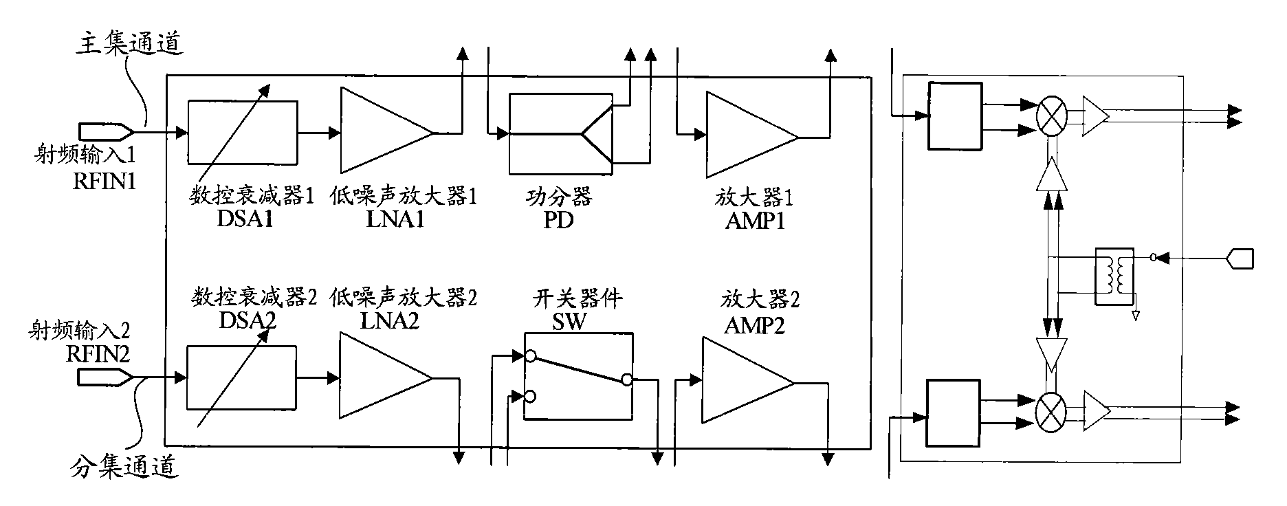
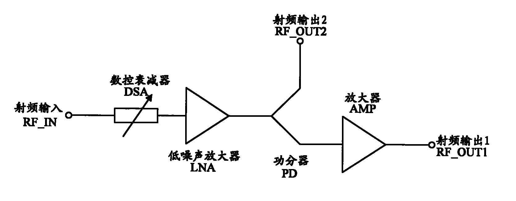
[0004] In the process of realizing that the above-mentioned receiver supports multiple applications, the inventors found at least the following problems in the prior art: the insertion loss of the DSA is relatively large, which directly deteriorates the noise figure of the front end of the receiver, and has a relatively large impact on the gain factor of the link. Large impact, the impact of the insertion loss of the PD and SW of the LNA post-stage on the noise figure cannot be ignored
In this way, in order to ensure the performance of each application module, the mutual matching between modules and the performance index of the receiver, the requirements for the noise, gain and linearity of each module are relatively high, and the design is difficult

Method used


Image

  • Amplifying device and signal processing method based on same
  • Amplifying device and signal processing method based on same
  • Amplifying device and signal processing method based on same

Examples


Embodiment 1

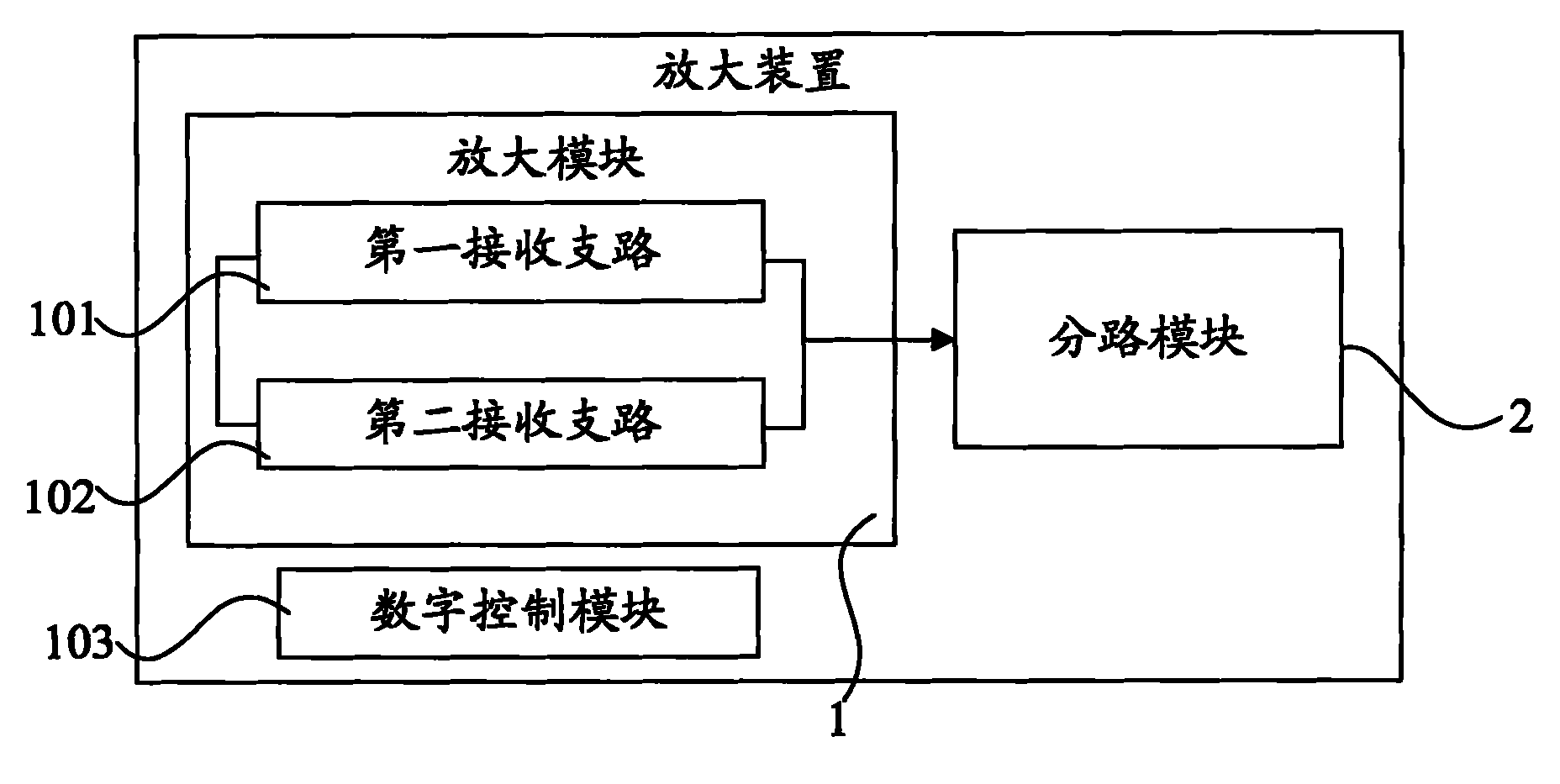
[0033] The amplifying device provided in this embodiment can be placed in a receiver, and the receiver can include but not limited to a communication tower top receiver, such as Figure 4 As shown, it includes an amplifying module 1, and the amplifying module 1 includes two receiving branches, a first receiving branch 101 and a second receiving branch 102; wherein, the first receiving branch 101 is used when the input signal has been amplified by the previous stage The input signal is attenuated and amplified; the second receiving branch 102 is used to amplify the input signal when the input signal has not been amplified by the previous stage.

[0034] In addition, the amplifying device provided in this embodiment further includes a branching module 2 coupled with the amplifying module 1 for cabinet-combining application of the input signal processed by the amplifying module 1 .

[0035] It should be noted here that the amplifying device provided in this embodiment further inc...

Embodiment 2

[0044] The amplifying device provided in this embodiment is a master and a dual-channel receiver from a set, such as Figure 5 The block diagram shown and Figure 6 In the system architecture diagram, the receiver of the present embodiment includes a main set amplification module 31, a main set splitting module 32 coupled with the main set amplification module 31; also includes a slave set amplification module 41, and a slave set amplification module 41 The coupled slave set shunt module 42 .

[0045] Wherein, both the main set amplification module 31 and the slave set amplification module 41 adopt the functional structure of the amplification module 1 in the first embodiment, including two receiving branches, wherein, the two receiving branches of the main set amplification module 31 are connected in parallel with each other; One of the receiving branches includes a digitally controlled attenuator 311 and a third low-noise amplifier 312, which are used to attenuate and ampli...


PUM


Abstract

An amplifying device and a signal processing method based on an amplifying device are provided, capable of reducing performance requirements of modules and reducing design difficulty of the modules. The amplifying device includes at least one amplifying module, including two receiving paths, in which a first receiving path is configured to attenuate and amplify an input signal after the input signal is pre-amplified, and a second receiving path is configured to amplify the input signal when the input signal is not pre-amplified. The signal processing method based on the amplifying device is further provided. The amplifying device and the signal processing method may be applied in a communication network system.

Description

technical field [0001] The invention relates to the technical field of communication, in particular to an amplifying device and a signal processing method based on the amplifying device. Background technique [0002] The receiver of the base station needs to support multiple application scenarios at the same time, including support for tower placement applications, support for interconnection and cabinet applications, and support for main and diversity dual-channel applications. In order to support the above applications at the same time, the front-end of the receiver needs to include modules supporting each application, and each module needs to be matched with each other. Therefore, the number of front-end modules of the receiver is large and the links are complicated. [0003] The tower amplifier in the tower amplifier application usually refers to the tower mounted amplifier, which is a low noise amplifier (LNA, Low Noise Amplifier) ​​installed on the top of the tower imm...

Claims


Application Information

Patent Timeline
Patent Type & Authority Patents(China)
IPC IPC(8): H04B1/40H04B7/005H04B7/26H03F3/20
CPCH03F3/189H04B7/0825H04B7/15535
Inventor 胡新荣魏源杨帆曾令海王晨刘玲
Owner HUAWEI TECH CO LTD
Learn More