
Quasi-fluorescence LED illumination monomer and application thereof

A technology for LED lighting and LED substrates, applied in lighting applications, outdoor lighting, lighting devices, etc., can solve the problems of large optical path loss, not very strong lighting, insufficient lighting, and achieve improved light efficiency, uniform and soft light, and brightness. high effect

Active Publication Date: 2010-07-28
SHANGHAI CATA SIGNAL CO LTD
View PDF4 Cites 15 Cited by
  • Summary
  • Abstract
  • Description
  • Claims
  • Application Information

AI Technical Summary

Problems solved by technology

[0004] For example, in a typical scheme, two LED luminous bodies are arranged opposite to each other at both ends of the LED lamp tube, and double-sided reflective sheets or light-guiding materials or light-reflecting materials are arranged in the tube body. The light emitted by the LED luminous body passes through the double-sided Surface reflective sheets or light reflective materials are reflected or scattered by light guide materials, so as to be as close as possible to the light output mode of existing fluorescent lamps. Typical solutions of this type include LED fluorescent lamps disclosed in Chinese Invention Patent Publication No. CN101144591A, and Chinese Utility Model Patent Authorization Announcement No. CN200993322Y discloses LED fluorescent lamps, etc., but this type of LED fluorescent lamps is not very strong because of the small number of LED illuminants used, so it is difficult to adapt to daily lighting.
[0005] Another typical way is to mix a certain amount of astigmatism powder or light guide powder evenly into PC or PV lamp raw materials in the process of injection molding lamp tubes, and inject them into hollow lamp tubes. The light emitted by LED illuminants passes through PC or PV lamp tubes The PV light tube is transmitted. This kind of patent is like the LED fluorescent lamp with soft and multi-luminous angles disclosed in the Chinese utility model patent authorization announcement number CN201293218Y. not enough
[0006] Another typical method is to use an LED illuminant with an additional lens, such as a high-power LED fluorescent lamp disclosed by the Chinese utility model patent authorization announcement number CN201330956Y. However, this type of LED fluorescent lamp still fails to solve the above-mentioned related problems in LED fluorescent lamps.

Method used


Image

  • Quasi-fluorescence LED illumination monomer and application thereof
  • Quasi-fluorescence LED illumination monomer and application thereof
  • Quasi-fluorescence LED illumination monomer and application thereof

Examples


Embodiment 1

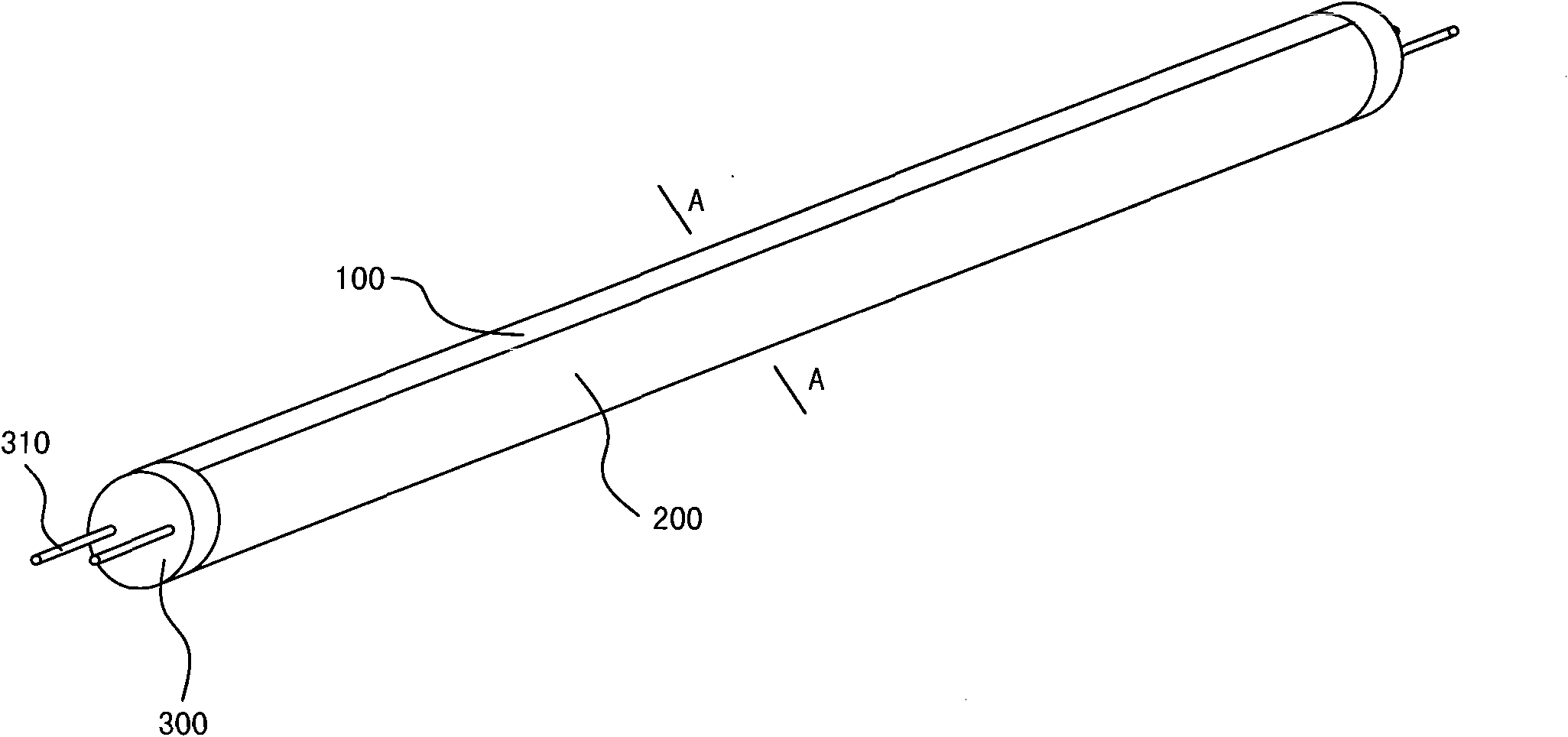
[0042] see figure 1 , a type of fluorescent LED fluorescent lamp of the present invention, including a lamp tube composed of an axial heat sink 100, a straight Fresnel condenser lens 500 and a light distribution lampshade 200, and the heat sink 100 is made of aluminum alloy. Lamp caps 300 are installed at both ends of the lamp tube, and electrodes 310 are provided on the lamp caps 300 .

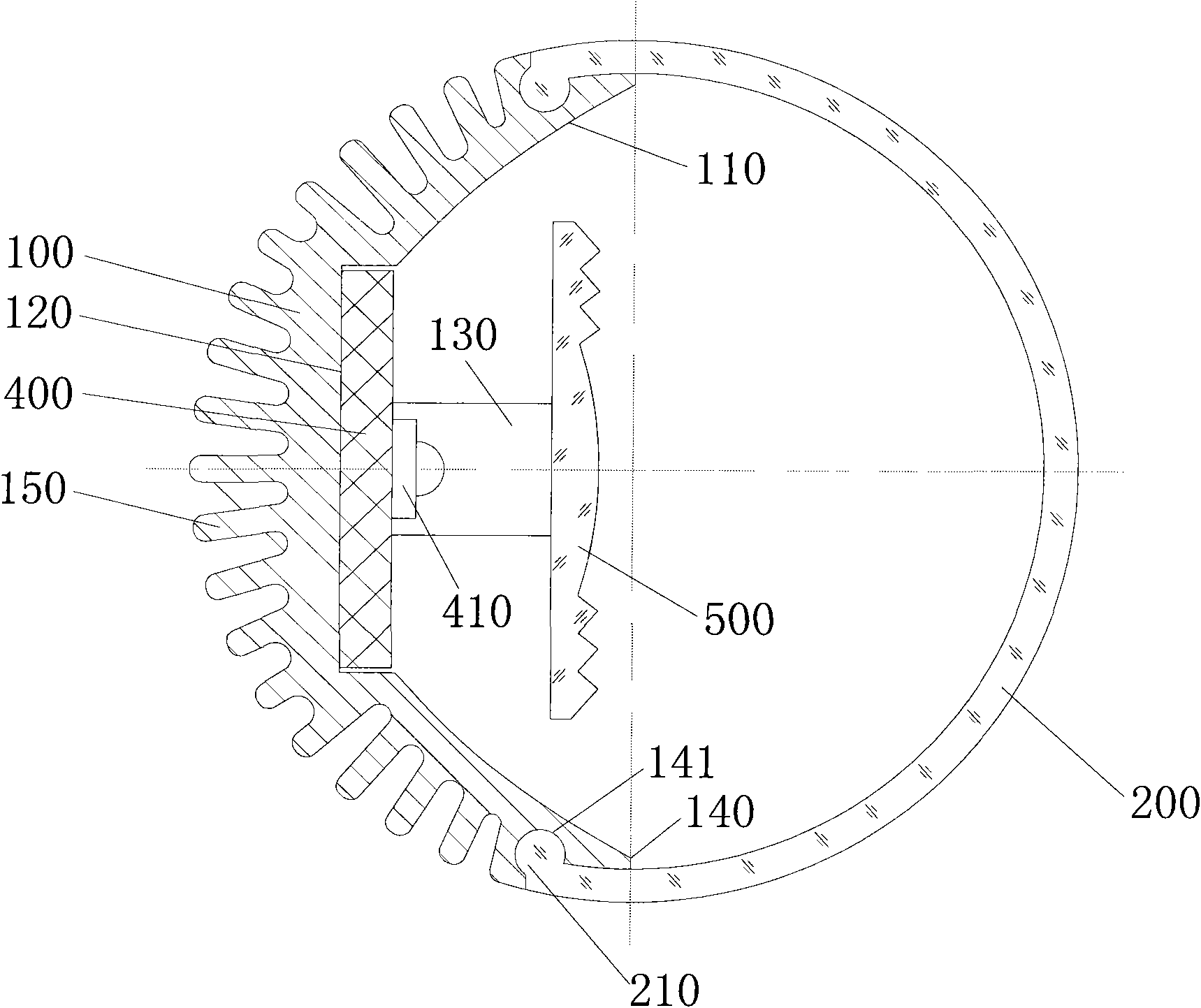
[0043] see figure 2 , the inner surface 110 of the heat sink 100 is a paraboloid with light reflection function, so as to reflect a part of the light emitted by the LED illuminant 410 . The inner surface 110 of the radiator 100 is provided with a strip-shaped installation groove 120 for the LED substrate 400 to be fitted. The LED substrate 400 is installed in the strip-shaped installation groove 120. The glue conducts heat. The LED substrate 400 is electrically connected to the electrode 310 fixed on the lamp cap 300 and extends along the axial direction of the radiator 100 . The LED sub...

Embodiment 2

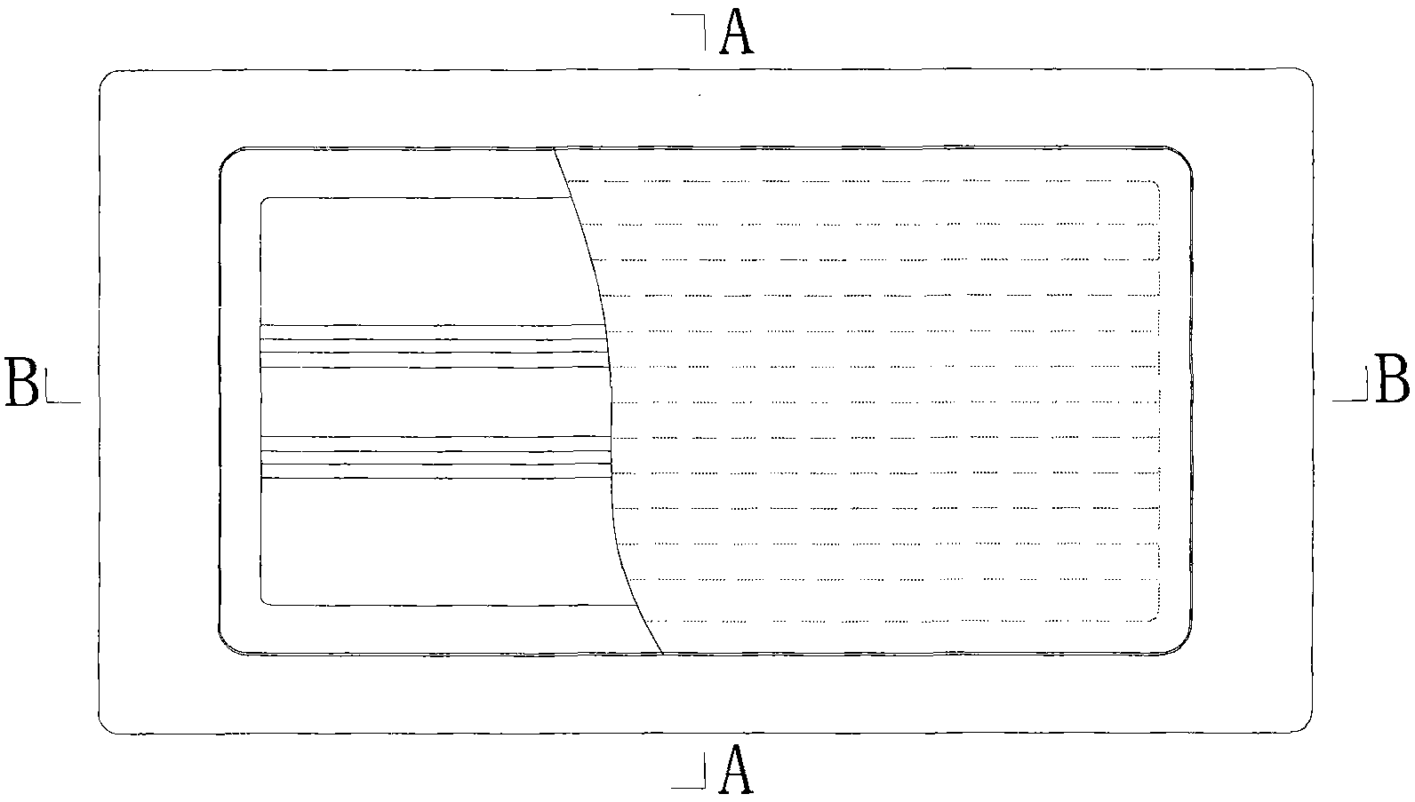
[0049] see Figure 3a to Figure 3c , The light-emitting unit of the warning light of the present invention includes a combination of a plate-shaped heat sink 100a, a straight Fresnel condenser lens 500, an LED substrate 400, and a light distribution lampshade 200a. The plate-shaped radiator 100a is made of aluminum alloy. On the inner surface 110a of the plate-shaped radiator 100a, a straight reflective bowl 160 is installed along the axial direction of the radiator 100a. The inner surface of the straight reflective bowl 160 is a parabolic surface 161 with a reflective effect. On the inner surface 110a of the heat sink 100a, and on the joint surface with the inner surface 110a of the heat sink 100a, thermal conductive adhesive is used for heat conduction.

[0050] The LED substrate 400 extends axially along the heat sink 100a, and the LED substrate 400 may be a whole strip, or several strips may be connected in series. Several LED illuminants 410 are packaged on the LED subs...

Embodiment 3

[0053] see Figure 4a to Figure 4c , The light-emitting unit of the navigation light of the present invention includes a combination of a plate-shaped heat sink 100b, a straight Fresnel condenser lens 500, an LED substrate 400, and a light distribution lampshade 200b. The plate-shaped radiator 100b is made of aluminum alloy. A straight reflective bowl 160 is installed on the inner surface 110b of the plate-shaped radiator 100b along the axial direction of the radiator 100b. The inner surface of the straight reflective bowl 160 is a paraboloid 161 with reflective effect. The LED substrate 400 is installed on the inner surface 110b of the plate-shaped heat sink 100b, and the bonding surface between the LED substrate 400 and the inner surface 110b of the heat sink 100b is conducted with heat conduction glue.

[0054] The LED substrate 400 extends axially along the heat sink 100b, and the LED substrate 400 may be a whole strip, or several strips may be connected in series. Sever...


PUM

PropertyMeasurementUnit
fluorescence quantum yieldaaaaaaaaaa

Abstract

The invention a quasi-fluorescence LED illumination monomer, which comprises a radiator, an LED substrate fixed on the radiator, and a plurality of LED illuminants encapsulated on the LED substrate. The first face of the radiator is provided with a paraboloid for reflecting light; a straight bar-type convex lens having radial converging effects is arranged in a space accommodated by the paraboloid; and the straight bar-type convex lens is positioned in front of the plurality of LED illuminants to radially converge but axially and diffusely emit partial light rays emitted by the plurality of LED illuminants. The illumination monomer radically solves the problems of spotted light source exposure, small illumination angles of optical paths, beaded light spots of the illuminant LED light source of lamps, visual dizziness caused by multiple projections formed by illuminating illuminated objects with a multiple-spot light source, dazzling light rays and the like existing in the conventional illumination lamps. The illumination monomer emits uniform and soft light rays, has high luminance in an illuminated area, has a light emitting mode which is basically not different from that of a conventional fluorescent lamp, and meets the requirements of people on use habit and approval for a long time. The invention also discloses various application of the quasi-fluorescence LED illumination monomer.

Description

technical field [0001] The invention relates to LED lighting / signal lamps, in particular to an LED lighting unit whose effect is similar to that of the existing fluorescent lamp fluorescent effect. The invention also relates to the application of the fluorescent LED lighting unit. Background technique [0002] Compared with traditional incandescent lamps, fluorescent lamps and other lighting fixtures, LED lighting has the characteristics of long life, high luminous efficiency, low power consumption and no phosphor pollution, and has a high degree of substitution. However, the existing LED lamp tubes available for lighting are all provided with circuit boards and LED arrays in the tube body of the lamp tube. On the tube wall, such LED fluorescent lamps have point light sources exposed, and the light path irradiation angle is small. The LED point light sources combined into fluorescent lamps are in the shape of beads, and the light is dazzling. The projection formed by the i...

Claims


Application Information

Patent Timeline
Patent Type & Authority Applications(China)
IPC IPC(8): F21S2/00F21S8/00F21S8/10F21V13/04F21V17/00F21V5/04F21V29/00F21V3/04F21V23/00F21W111/04F21W101/02F21W131/103F21Y101/02F21W107/10
CPCF21V31/005F21V5/007F21V5/045F21V7/06Y02B20/386F21V13/04F21W2111/043F21Y2101/02F21K9/17F21V29/225F21Y2103/003F21V29/004F21V29/2218F21V29/2262F21V7/005F21S4/003F21V5/008F21K9/27F21K9/68F21K9/69F21S4/20F21V29/745F21V29/75F21V29/763F21Y2103/10F21Y2115/10
Inventor 张文虎郑秋华
Owner SHANGHAI CATA SIGNAL CO LTD
Learn More