
Electromobile control device

A technology of electric vehicle control and equipment, applied in the field of electric vehicles, can solve the problems of large output power of control equipment, operation failure, poor heat dissipation performance, etc., to ensure the installation in place, ensure long-term work, and improve the effect of waterproof performance

Inactive Publication Date: 2014-03-19
TIANJIN SANTROLL ELECTRIC AUTOMOBILE TECH CO LTD
View PDF4 Cites 0 Cited by
  • Summary
  • Abstract
  • Description
  • Claims
  • Application Information

AI Technical Summary

Problems solved by technology

If the sealing is not good, the electric vehicle control equipment will enter the water, causing the circuit board components to short-circuit and fail; if the heat dissipation effect is not good, the circuit board will work for a long time, the temperature will rise beyond the maximum value of the components, and the components will be damaged, resulting in control The equipment does not work normally or even fails to operate. For high-power vehicles such as electric four-wheel vehicles and electric vehicles, due to the large output power and high heat generation of the control equipment, the requirements for heat dissipation performance are higher at this time.
[0003] The most common shell structure of control equipment on the market is that the shell is divided into two parts, the groove and the cover plate. The circuit board is put into the groove, and then the cover plate is covered. Due to the gap left at the upper and lower connections, water vapor can easily enter the cavity where the circuit board is located through this gap, causing the components of the circuit board to short-circuit and fail; at the same time, the outlet is exposed outside, which is not conducive to waterproofing
There is another type on the market that is the overall shell plus two end caps. The end cap on one side leaves a connector for wiring. At the same time, a "U"-shaped aluminum strip is placed in the overall shell. The two arms of the "U" are used to install the power tube. , the bottom of the "U" is used to place the circuit board. Since the heat of this structure is first transferred to the aluminum strip and then passed out through the shell, its heat dissipation performance is very poor, which is not conducive to ensuring the long-term normal operation of the control equipment. At the same time, its Waterproof effect is not good
In short, none of the structural forms of the electric vehicle control equipment in the prior art can better solve the problem of waterproof and heat dissipation, and these waterproof and heat dissipation problems have become a bottleneck technical problem restricting the development of the electric vehicle control equipment industry.

Method used


Image

  • Electromobile control device
  • Electromobile control device
  • Electromobile control device

Examples


Embodiment Construction

[0022] Embodiments of the present invention are described in further detail below in conjunction with the accompanying drawings:

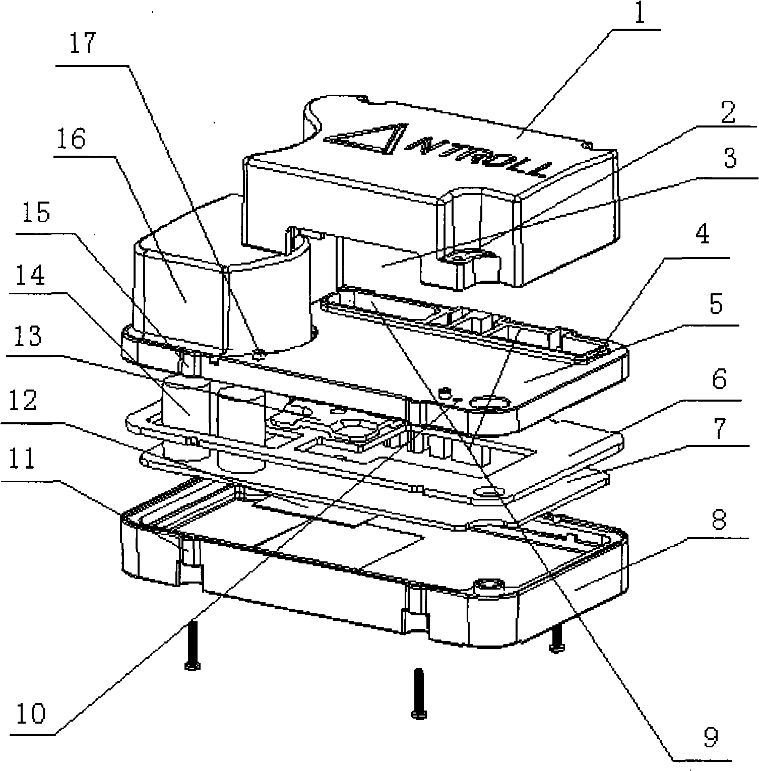
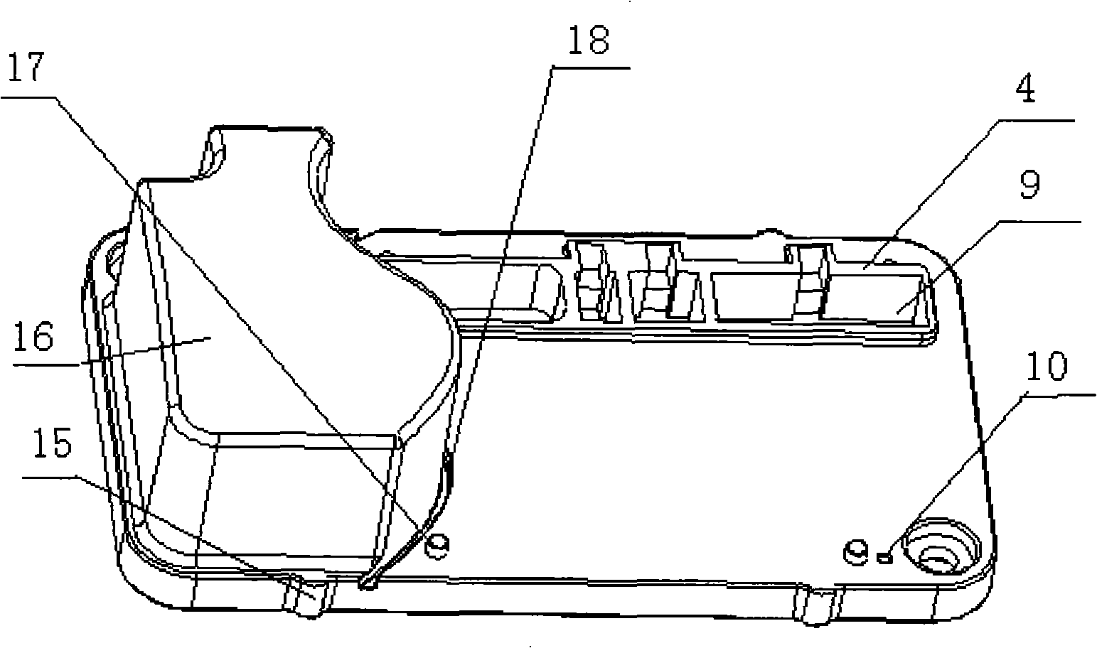
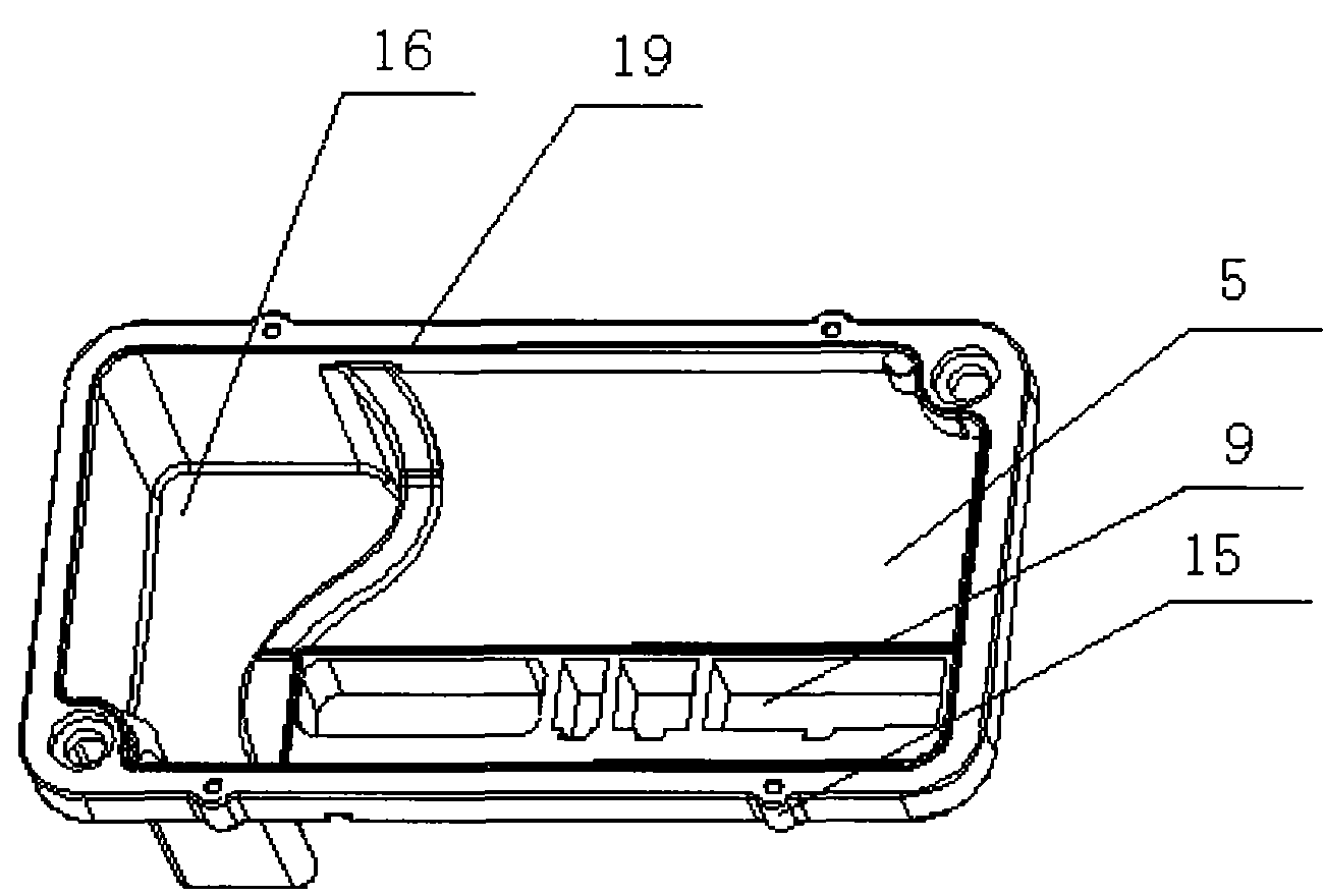
[0023] Such as Figure 1-8 As shown, 1 is the waterproof cover, 2 is the screw hole, 3 is the outlet hole, 4 is the water shield, 5 is the upper cover, 6 is the gasket, 7 is the circuit board, 8 is the bottom shell, and 9 is the outlet connector. Through hole, 10 is the screw hole, 11 is the screw hole, 12 is the cooling pad, 13 is the pressure plate, 14 is the connector, 15 is the screw hole, 16 is the cavity, 17 is the positioning pin, 18 is the water guide groove, 19 is the convex Rib, 20 is the bracket, 21 is the limit protrusion, 22 is the screw hole, 23 is the positioning groove, 24 is the screw hole, 25 is the threaded connector, 26 is the power tube, 27 is the screw hole, 28 is the depression place.

[0024] The electric vehicle control device of the present invention comprises an upper cover 5 and a bottom case 8, a circuit board 7 is ar...


PUM


Abstract

The invention discloses an electromobile control device and aims to provide an electromobile control device which has the advantages of good sealability, good radiating performance and convenient maintenance. The electromobile control device comprises a shell and a circuit board, wherein the shell comprises an upper cover and a bottom case; the circuit board is arranged between the upper cover and the bottom case; the internal surface of the bottom case is provided with a ring of support table used for supporting the circuit board; a power tube of the circuit board is arranged below the circuit board; the radiating surface of the power tube tightly presses the upper surface of the bottom case; a radiating pad is arranged between the upper surface of the bottom case and the power tube and used for conducting heat of the power tube; a sealer is arranged between the circuit board and the upper cover; a press plate is arranged between the sealer and the upper cover; and a connecting piece with a screw structure orderly penetrates through the press plate, the sealer and the circuit board and is screwed in the bottom case. The invention has the advantages of good sealability and waterproofness, convenient maintenance and good radiating performance, and is a substitute of the prior electromobile control device.

Description

technical field [0001] The invention belongs to equipment in the field of electric vehicles, and more specifically is a control equipment applied to electric vehicles. Background technique [0002] At present, electric vehicles mainly include electric bicycles, electric tricycles, electric four-wheel vehicles, electric scooters, electric shopping carts, etc. Electric vehicle control equipment, as the control center part of electric vehicles, needs to have good waterproof, shockproof and heat dissipation performance. If the sealing is not good, the electric vehicle control equipment will enter the water, causing the circuit board components to short-circuit and fail; if the heat dissipation effect is not good, the circuit board will work for a long time, the temperature will rise beyond the maximum value of the components, and the components will be damaged, resulting in control The equipment does not work normally or even fails to operate. For high-power vehicles such as ele...

Claims


Application Information

Patent Timeline
Patent Type & Authority Patents(China)
IPC IPC(8): H05K5/06H05K7/20
Inventor 孔昭松孙海泉
Owner TIANJIN SANTROLL ELECTRIC AUTOMOBILE TECH CO LTD
Learn More