Pneumatic experimental table for loading electrical actuator

A technology of electric actuators and test benches, which is applied in the direction of electric power measurement through current/voltage, instruments, and electric devices, etc., which can solve the problems of long maintenance cycle of pneumatic brakes, narrow applicable torque range, and increased magnetic force of magnetic powder. Achieve fast loading, fast response, easy maintenance, and compact size

Inactive Publication Date: 2013-10-30
SHENZHEN MAXONIC AUTOMATION CONTROL CO LTD
View PDF4 Cites 0 Cited by
  • Summary
  • Abstract
  • Description
  • Claims
  • Application Information

AI Technical Summary

Problems solved by technology

[0009] Third, the torque controllability of the pneumatic brake is good at low speed (below 15 rpm); the magnetic powder brake is suitable for high-speed occasions, and it is most commonly used to test the high-speed motor as the load of the dynamometer, and it is used for low-speed operation after multi-stage deceleration Actuators with poor controllability and unstable load
[0010] Fourth, the multiplicity of the applicable torque range of the air pressure brake. The same type of brake can use three friction plates with different friction coefficients of high, medium and low, which can easily change the applicable torque in a large range; the same type of magnetic powder brake can be used The magnetic powder does not change much, and the applicable torque range is narrow
[0011] Fifth, the air pressure brake has a long maintenance period and is easy to maintain. The friction plate can be replaced on the equipment, and the service life is 45,000 to 60,000 hours; the magnetic powder brake can only be used within the allowable slip power, and maintenance is troublesome, and the service life is 5,000 to 8,000 hours.
[0012] Sixth, pneumatic loading can realize emergency braking in a short period of time. As long as the air circuit is connected, the gas will fill the brake cavity immediately, and the full pressure can be reached in about 0.05s; Large process, loses advantage in emergency braking

Method used


Image

  • Pneumatic experimental table for loading electrical actuator
  • Pneumatic experimental table for loading electrical actuator
  • Pneumatic experimental table for loading electrical actuator

Examples


Embodiment Construction

[0028] Embodiments of the present invention will be further described below in conjunction with the accompanying drawings.

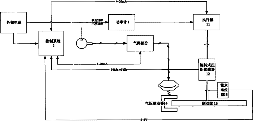
[0029] The electric actuator test bench of the present invention adopts a pneumatic loading method, that is, the pneumatic brake is used as the load of the actuator. The test bench has a compact structure, can reach the maximum load in a very short time (<0.1s), has good low-speed and high-speed torque controllability, does not need water cooling and forced air cooling, and has high temperature resistance.

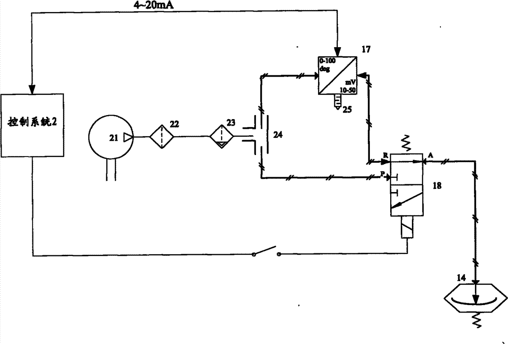
[0030] The test bench uses 0-8Bar compressed air commonly used in factories and laboratories as the power source, and realizes slow loading and fast loading by switching the air circuit and adjusting the given air pressure, and at the same time realizes variable speed release of the load.

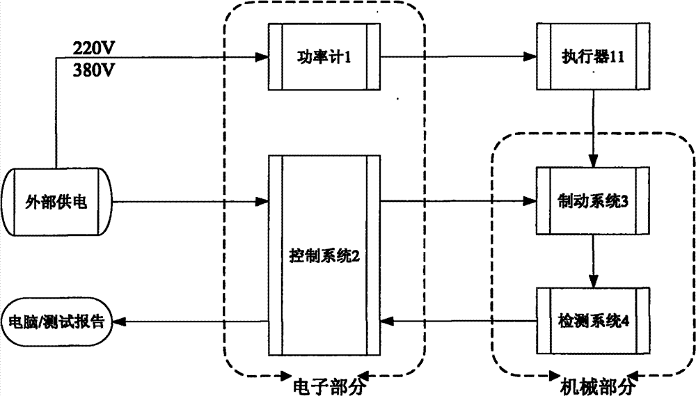
[0031] Such as figure 1 As shown in the system block diagram, the main components of the test bench include:

[0032] The brake system 3 includes a brake disc 1...


PUM


Abstract

The present invention discloses a pneumatic experimental table for loading an electrical actuator. A brake system for loading an electrical actuator comprises an electrical / pneumatic converter for regulating loading air pressure, a change valve for switching loading air circuits, a brake disk and a pneumatic brake. The brake disk is driven by the output shaft of the electrical actuator to rotate. Friction is loaded on the brake disk by the pneumatic brake under the action of compressed air. The following modes can be selected by the change valve: the pressure of the compressed air acts on the pneumatic brake after the adjustment of the electrical / pneumatic converter to exert adjustable friction on the brake disk, and the slow loading mode of the electrical actuator is realized; the compressed air directly acts on the pneumatic brake to exert maximum friction on the brake disk, and the quick loading mode of the electrical actuator is realized; the air pressure acting on the pneumatic brake is controlled by the electrical / pneumatic converter, and the variable speed unloading mode of the electrical actuator is realized. The present invention has the advantages that quick loading, slow loading, variable speed unloading and multiple modes of load control, which are required in the test process, can all be realized.

Description

technical field [0001] The invention relates to the technical field of testing equipment, in particular to a pneumatic loading test bench for testing electric actuators. [0002] Suitable for multi-turn actuator load testing, or angular rotation actuator load testing. It can be widely used in electric actuator production enterprises and laboratories, especially for electric actuators whose test output torque is within 20000Nm. Background technique [0003] As a test bench for actuators, the most important design is what kind of load method to use and how to design the load. [0004] At present, in factories and experimental units, it is especially common to use electromagnetic / magnetic powder brakes as load loading. Electromagnetic / magnetic powder brakes have a narrow range of use, small torque, and high speed, and are not suitable for the detection of high torque and low speed of electric actuators. [0005] With the advancement of science and technology, the pneumatic b...

Claims


Application Information

Patent Timeline
Patent Type & Authority Patents(China)
IPC IPC(8): G01L3/04G01R19/00G01R21/06G01B7/30G01P3/46
Inventor 傅宇晨袁敏勋袁菲
Owner SHENZHEN MAXONIC AUTOMATION CONTROL CO LTD
Why Eureka
Try Eureka