Vehicle-mounted AC/DC charging and driving circuit topology based on winding reconfiguration of reluctance motor

An AC-DC charging and reluctance motor technology, applied in the field of power electronics, can solve the problems of inability to obtain smooth and wide torque boost, reduction of effective volume, increase in manufacturing cost, etc., so as to prolong battery life and save manufacturing cost. and interior space, the effect of ensuring safety

Active Publication Date: 2020-02-21
ANHUI UNIV OF SCI & TECH
View PDF7 Cites 0 Cited by
  • Summary
  • Abstract
  • Description
  • Claims
  • Application Information

AI Technical Summary

Problems solved by technology

However, the driving circuit and charging circuit of traditional electric vehicles are separated, which reduces the effective volume of electric vehicles and increases the manufacturing cost.
The motor drive power supply does not contain a front-end DC / DC converter, which makes the motor's voltage requirements for the battery supply too strict, and it is impossible to obtain a smooth and wide torque boost
In terms of charging, a car is generally only suitable for a single fixed charging pile, which will cause a lot of inconvenience in daily life

Method used


Image

  • Vehicle-mounted AC/DC charging and driving circuit topology based on winding reconfiguration of reluctance motor
  • Vehicle-mounted AC/DC charging and driving circuit topology based on winding reconfiguration of reluctance motor
  • Vehicle-mounted AC/DC charging and driving circuit topology based on winding reconfiguration of reluctance motor

Examples


Embodiment Construction

[0028] The vehicle-mounted AC and DC charging circuit based on the reconfiguration of reluctance motor windings according to the present invention will be further described below in conjunction with the accompanying drawings and specific embodiments.

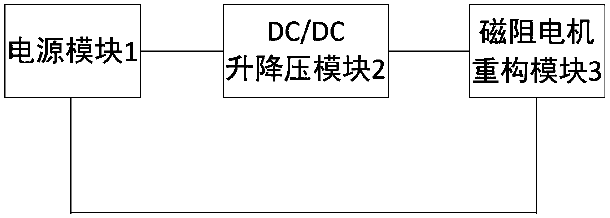
[0029] figure 1 As shown, the vehicle-mounted AC / DC charging circuit based on the reconfiguration of reluctance motor windings in the present invention includes a power supply module 1 , a DC / DC buck-boost module 2 and a reluctance motor reconfiguration module 3 .

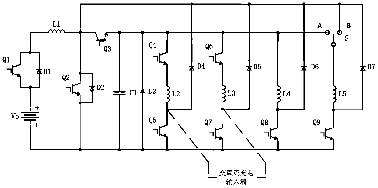
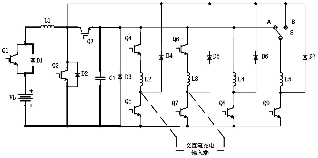
[0030] figure 2 As shown, this circuit topology includes a lithium battery (V b ), the first inductance (L 1 ), the first capacitor (C 1 ), the first switch tube to the ninth switch tube (Q 1 -Q 9 ), the first diode to the eighth diode (D 1 -D 8 ), the SPDT switch (S), and the reluctance motor winding (L 2 , L 3 , L 4 , L 5 ) and connect as shown. The first to ninth switch tubes (Q 1 -Q 9 ) are controlled by PWM. Among them, the first switching tube Q...


PUM


Abstract

The invention discloses reluctance motor winding reconfiguration-based vehicle-mounted alternating current-direct current charging and driving circuit topology. The circuit topology comprises a powersupply module, a DC / DC voltage boost-buck module and a reluctance motor reconfiguration module which are connected mutually. Through the reconfiguration reluctance motor, the circuit can work in a charging mode or a charging mode, and the manufacturing cost and the internal space of an electric vehicle can be effectively lowered and reduced; in addition, by reducing the number of switching tubes,the circuit reliability is improved; on the aspect of driving, the circuit topology can obtain high-speed and stable starting torque and wider torque range, and electric energy can be fed back in automobile deceleration or downhill, so that battery duration can be prolonged; on the aspect of charging, the circuit topology can lower limitation on the types of external charging piles, and the voltage can be lowered when the charging voltage is too high, so that charging safety can be ensured; and power factor regulation in the alternating current charging mode can be realized, so that the charging efficiency can be improved.

Description

technical field [0001] The invention relates to the technical field of power electronics, in particular to an electric vehicle charging and driving integrated device with wide application, faster speed increase, longer battery life and PFC correction function. Background technique [0002] In order to reduce vehicle exhaust emissions and environmental pollution, under the conditions of using clean energy and reducing costs, electric vehicles have the advantages of high drive energy conversion efficiency, strong regenerative braking capability of motors, low noise and vibration. However, the driving circuit and charging circuit of traditional electric vehicles are separated, which reduces the effective volume of electric vehicles and increases the manufacturing cost. The motor drive power supply does not contain a front-end DC / DC converter, which makes the motor's voltage requirements for the battery power supply too strict, and it is impossible to obtain a smooth and wide to...

Claims


Application Information

Patent Timeline
Patent Type & Authority Patents(China)
IPC IPC(8): H02M3/158H02M1/42H02J7/00B60L53/20
CPCB60L53/24H02J7/0068H02M1/4208H02M3/158Y02T10/70Y02T10/7072Y02T10/72Y02T10/92Y02T90/14
Inventor 祝龙记王琦
Owner ANHUI UNIV OF SCI & TECH
Why Eureka
Try Eureka