Power transmission unit

A power transmission and power technology, which is applied in transmission devices, fluid transmission devices, belts/chains/gears, etc., can solve the problems of narrow torque conversion range and low efficiency, and achieve a wide torque conversion range, high efficiency and simple structure. Effect

Inactive Publication Date: 2017-05-03
SHANGLING HLDG CO LTD
View PDF8 Cites 0 Cited by
  • Summary
  • Abstract
  • Description
  • Claims
  • Application Information

AI Technical Summary

Problems solved by technology

[0002] Hydraulic transmission devices, such as hydraulic torque converters, are widely used, but the torque range is narrow and the efficiency is low. Therefore, it is necessary to invent a new hydraulic transmission device

Method used


Image

  • Power transmission unit
  • Power transmission unit
  • Power transmission unit

Examples


Embodiment 1

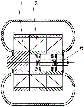
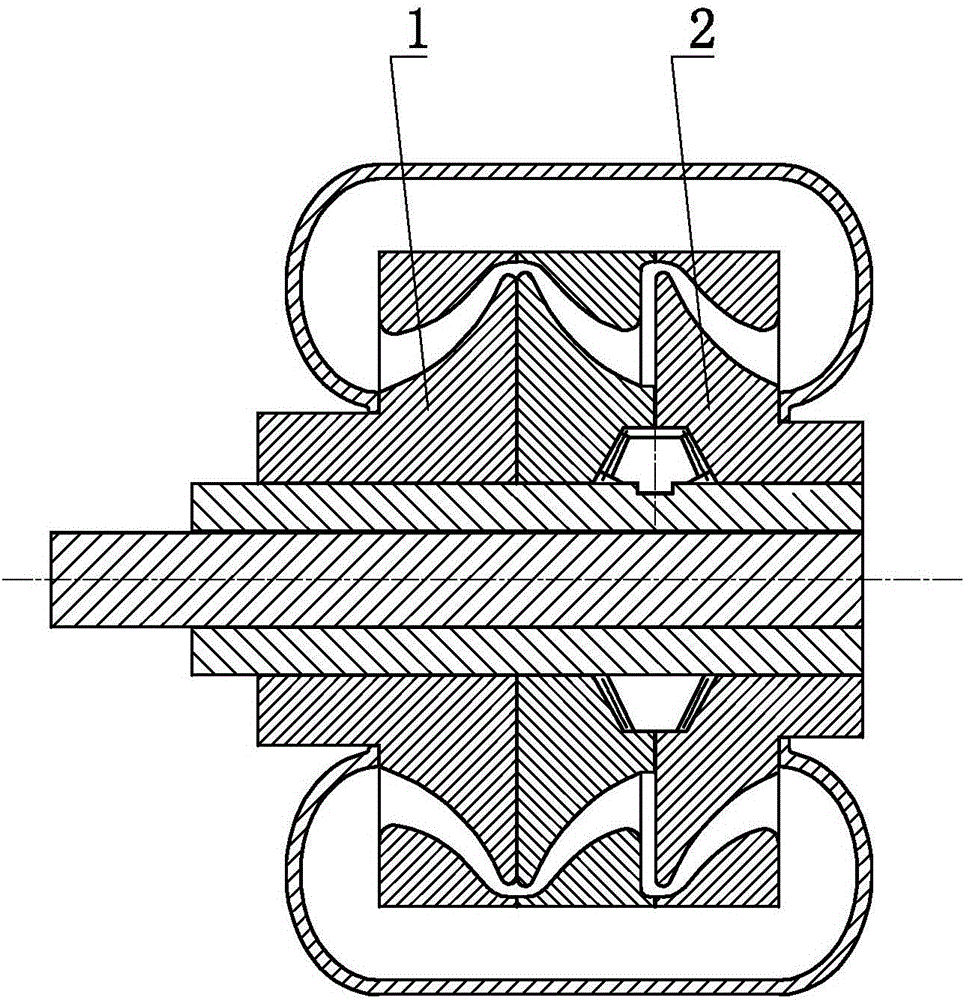
[0034] Such as figure 1 , figure 2 The power transmission unit shown includes a pump wheel 1 and a turbine wheel 2, the pump wheel 1 and the turbine wheel 2 are arranged correspondingly, the turbine wheel 2 is set to more than two stages, and the pump wheel 1 and the turbine wheel 2 form a fluid The loop transmits power.

Embodiment 2

[0036] The shown power transmission unit, on the basis of Embodiment 1, further selectively sets that the turbine 2 includes more than two moving impellers 3 coaxially arranged and two adjacent moving impellers 3 Static impeller.

Embodiment 3

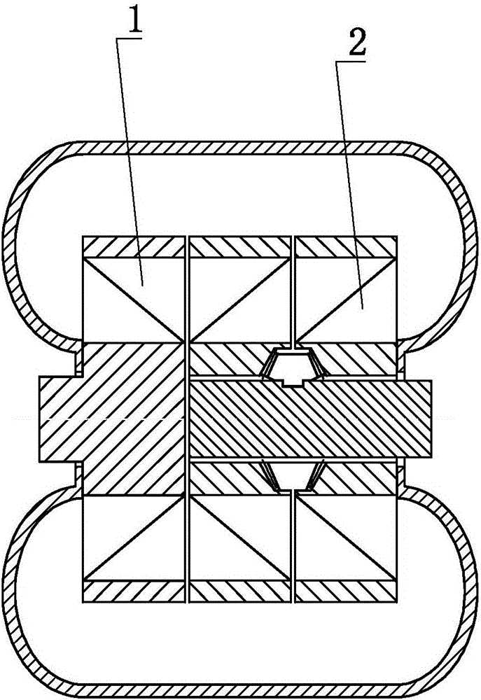
[0038] Such as image 3 In the power transmission unit shown, on the basis of Embodiment 1, the turbine 2 is further selectively configured to include more than two pairs of rotating impellers 3 .


PUM


Abstract

Disclosed is a power transmission unit. The power transmission unit comprises a pump impeller and a turbine, wherein the pump impeller and the turbine are correspondingly arranged, the stage of the turbine is set to be more than two stages, and a fluid loop is formed by the pump impeller and the turbine to transmit the power. The power transmission unit is simple in structure, wide in variable torque range and high in efficiency.

Description

technical field [0001] The invention relates to the field of thermal energy and power, in particular to a power transmission unit. Background technique [0002] Hydraulic transmission devices, such as hydraulic torque converters, are widely used, but the torque range is narrow and the efficiency is low. Therefore, it is necessary to invent a new hydraulic transmission device. Contents of the invention [0003] In order to solve the above problems, the technical scheme proposed by the present invention is as follows: [0004] A power transmission unit includes a pump wheel and a turbine, the pump wheel and the turbine are arranged correspondingly, the turbine is set in more than two stages, and the pump wheel and the turbine form a fluid circuit to transmit power. [0005] A power transmission unit includes a pump wheel and a turbine, the pump wheel and the turbine are connected in series, the turbines are arranged in more than two stages, and the pump wheel and the turbin...

Claims


Application Information

Patent Timeline
Patent Type & Authority Applications(China)
IPC IPC(8): F16H47/06
CPCF16H47/06
Inventor 靳北彪
Owner SHANGLING HLDG CO LTD
Why Eureka
Try Eureka