
Smelting furnace

A furnace and furnace chamber technology, applied in the field of kiln equipment and metallurgy, can solve the problems of energy waste, high flue gas temperature, and increase the cost of steelmaking, and achieve the effects of reducing energy consumption, uniform temperature, and improving combustion power

Inactive Publication Date: 2010-06-23
陈久斌
View PDF0 Cites 4 Cited by
  • Summary
  • Abstract
  • Description
  • Claims
  • Application Information

AI Technical Summary

Problems solved by technology

The carbon monoxide content in the cupola flue gas is also high, and the flue gas temperature is very high, all of which bring a lot of energy waste
Blast furnace ironmaking requires preprocessing of raw materials such as ore sintering and pelletizing, which increases energy consumption and expenditure; it cannot directly use low-grade ore raw materials, which increases raw material costs and cannot make full use of resources; precious metals in ores cannot be extracted, resulting in waste of resources
Ironmaking and steelmaking cannot be completed simultaneously, and molten iron transfer and secondary blowing are required, which increases smelting costs; steel slag treatment is also troublesome, increasing steelmaking costs
Glass furnaces, ceramic frit furnaces, and sodium hydroxide furnaces generally have defects such as high energy consumption and insufficient environmental protection.

Method used


Image

  • Smelting furnace
  • Smelting furnace
  • Smelting furnace

Examples


Embodiment Construction

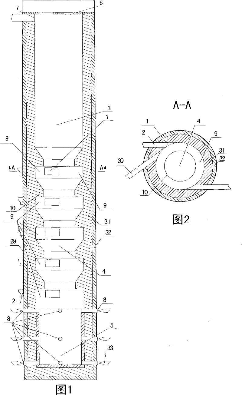
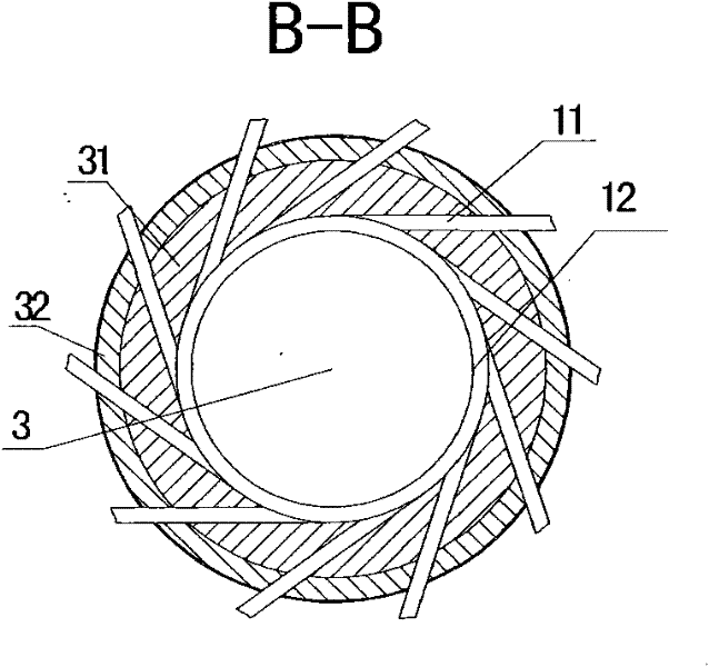
[0016] The main structure of the present invention is: a smelting furnace, comprising: a furnace chamber 29, a refractory material 31, an insulating material 32, a fan, a pipeline 30, an ignition device, a fuel supply device, and a discharge device 33, and at least one inlet is arranged on the side wall of the furnace chamber 29 The gas port 1 and the air inlet 1 are connected to at least one air intake passage 2, the air intake passage 2 is connected to the fan, and a plurality of fire passages 9 are arranged on the side wall of the furnace chamber, the air inlet 1 communicates with the fire passage 9, and the furnace chamber 29 is provided with a heating Chamber 3 and smelting chamber 4, the lower part of heating chamber 3 is connected to smelting chamber 4, the lower part of smelting chamber 4 is provided with hearth 5, the upper part of heating chamber 3 is provided with at least one heating chamber feed port 6, and the upper part of heating chamber 3 is provided with at lea...


PUM


Abstract

The invention relates to a smelting furnace, comprising a furnace chamber, fire-resistant materials, insulation materials, a fan, channels, an ignition device, a fuel supply device and a discharging device. At least one air inlet is arranged on the side wall of the furnace chamber, at least one air inlet passage is connected with the air inlet, and the air inlet passage is connected with the fan; the side wall of the furnace chamber is provided with a plurality of fire paths, and the air inlet is communicated with the fire paths; the furnace chamber is provided with a heating chamber and a smelting chamber, wherein the lower part of the heating chamber is communicated with the smelting chamber, the lower part of the smelting chamber is provided with a hearth, at least one feeding inlet of the heating chamber is arranged on the upper part of the heating chamber, and at least one air outlet is arranged on the upper part of the heating chamber; at least one discharge port of the hearth is formed in the hearth; and the discharge port of a smelting tank is provided with the discharging device. The invention is characterized in that a plurality of fuels and raw coal can be used in the smelting furnace; smelting iron and smelting steel can be synchronously completed; steel slag is no needed to be removed; the heat produced by smelting steel is fully utilized, waste gases are uniformly treated; smelting iron, casting iron, smelting steel and casting steel can be directly carried out by using ores and the like; glasses, ceramic clinker, sodium silicate and the like can be produced in the smelting furnace; and noble elements can be refined, refining can be achieved and the revolution of materials is brought out. The invention has the advantages of saving energy, protecting environment and smelting iron without coke.

Description

technical field [0001] The invention relates to the fields of metallurgy and kiln equipment such as blast furnaces, cupolas, smelting furnaces, reverberatory furnaces, and melting furnaces, in particular to a smelting melting furnace. Background technique [0002] Existing blast furnaces, cupolas, smelting furnaces, reverberatory furnaces, melting furnaces, etc. generally have exhausted flue gas temperatures that are too high, heat energy utilization rate is low, energy consumption is large, and pollution is serious. Coke must be used in blast furnaces and cupolas. Coke resources are limited and expensive. Coke production pollutes the environment and increases energy consumption. During the use of the cupola, the flue gas rises to the sky, causing serious pollution. A large amount of blast furnace gas is produced in the blast furnace production. If it is not used properly, it will inevitably lead to a large amount of energy waste. Blast furnace gas utilization equipment req...

Claims


Application Information

Patent Timeline
Patent Type & Authority Applications(China)
IPC IPC(8): F27B1/04F27B1/10F27B1/14F27B1/16F27B1/21
CPCY02P40/60
Inventor 陈久斌
Owner 陈久斌
Learn More