
Self-cleaning sink of plastic extruder

A plastic extruder, self-cleaning technology, applied in the field of plastic production equipment, can solve the problems of changing technical solutions, undiscovered structure, water overflow in the tank, etc., to achieve the effect of improving cleaning quality, ensuring product quality, and stable water flow

Inactive Publication Date: 2010-06-23
SHANGHAI KINGFA SCI & TECH
View PDF0 Cites 4 Cited by
  • Summary
  • Abstract
  • Description
  • Claims
  • Application Information

AI Technical Summary

Problems solved by technology

[0004] 1. The water pressure sent into the water inlet is unstable, and a water vortex is formed during the backflow, which is not conducive to the smooth passage of the material strip through the water tank; in severe cases, the water flow will directly spray out from the water inlet to break the material strip
[0005] 2. Impurities adhere to and disperse in the sink, which is not conducive to cleaning
[0006] 3. A large amount of impurities generated in the production block the water outlet, and the water in the tank is easy to overflow due to the continuous water inflow into the water inlet
[0007] 4. There is a lot of dust on the water surface, which can easily cause product appearance pollution
[0008] According to the patent search, there is only a technical solution to change the material of the cooling water tank from metal to plastic, but no technical solution to change the structure of the above defects has been found.

Method used


Image

  • Self-cleaning sink of plastic extruder
  • Self-cleaning sink of plastic extruder
  • Self-cleaning sink of plastic extruder

Examples


Embodiment 1

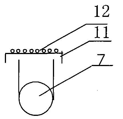
[0038] Plastic extruder self-cleaning sink (8), made of stainless steel, rectangular. One end of the lower part of the water tank (8) is provided with a water inlet pipe (4), and the water inlet pipe (4) is provided with a flat plate (9) and a mesh plate (10). The other end is provided with a water outlet pipe (7), the water outlet pipe (7) is provided with a filter screen cover (11), and the filter screen cover (11) is provided with a mesh plate (12). The upper part of the side of the water tank (8) is provided with a length of 10 cm and an overflow hole (6) of 5 cm in width, and the bottom of the side overflow hole (6) of the water tank (8) is provided with an overflow tank (1); (6) is positioned higher than the overflow tank (1); the bottom of the overflow tank (1) is provided with a water outlet (2). A miscellaneous plate (13) is arranged in the overflow tank, and a sponge (14) is arranged on the miscellaneous plate (13).

[0039] After the cooling water flows into the w...

Embodiment 2

[0043] Plastic extruder self-cleaning sink (8), made of stainless steel, round. The upper part of the circumference is provided with an overflow hole (6) with an arc length of 10 cm and a height of 5 cm. The outside of the garden-shaped tank (8) is provided with a circular overflow tank (1). All the other structures and operations are the same as in Embodiment 1.


PUM


Abstract

The invention relates to plastic production equipment, in particular to a self-cleaning water tank of a plastic extruder. The cooling water tank of the existing plastic extruder has the following defects that: the water feeding pressure is not stable; the impurities can not be cleaned conveniently; the product appearance can be easily polluted; and the water in the tank can easily overflow. In the technical scheme of the invention, a water feeding pipe (4) and a water discharging pipe (7) are respectively on the lower parts of both ends of a water tank (8); and a flat plate (9) and a meshed plate (10) are arranged on the water feeding pipe (4). A filter screen cover (11) is arranged on the water discharging pipe (7), and a meshed plate (12) is arranged on the filter screen cover (11). The upper part of the side face of the water tank (8) is provided with an overflow hole (6), an overflow water tank (1) is arranged below the overflow hole (6); an impurity collecting plate (13) is arranged in the overflow tank, and a sponge (14) is arranged on the impurity collecting plate (13). The invention has the advantages that: the water feeding flow is stable, the impurities in the water tank can be easily cleaned, the cleanness of cooling water can be maintained, and the water in the tank can not overflow into the environment.

Description

technical field [0001] The invention belongs to plastic production equipment, in particular to a plastic extruder self-cleaning water tank for self-cleaning the strips extruded by the plastic extruder. Background technique [0002] In the production of modified plastics, the strips extruded from the high-temperature melting of the extruder can only be fed into the pelletizer for pelletizing after cooling down and hardening, and then can be processed in the next step. The freshly extruded strips need to be cooled by a water tank filled with cooling water to achieve a hardening effect. Products with high value and high quality requirements also have high requirements on appearance, and external pollution directly affects the pass rate of products. The cooling water tank used in the production of the prior art is a tank whose overall shape is similar to a cuboid. One end of the water tank is located directly below the head of the extruder, and the width of the water tank is sl...

Claims


Application Information

Patent Timeline
Patent Type & Authority Applications(China)
IPC IPC(8): B29C47/88
CPCB29C48/919
Inventor 张淋图赵宇刘鹏陈延安
Owner SHANGHAI KINGFA SCI & TECH
Learn More