
Method for rolling grinding of ground surface of single crystal silicon

A monocrystalline silicon grinding technology, which is applied in grinding/polishing equipment, machine tools suitable for grinding workpiece planes, machine tools suitable for grinding workpiece edges, etc., can solve the problems of time-consuming and labor-consuming, difficult to control rotation, Heavy weight and other problems, to achieve the effect of simplifying the grinding process, improving quality and improving work efficiency

Active Publication Date: 2010-06-23
海宁市日进科技有限公司
View PDF5 Cites 7 Cited by
  • Summary
  • Abstract
  • Description
  • Claims
  • Application Information

AI Technical Summary

Problems solved by technology

[0005] Since the four faces and four arc surfaces of the single crystal silicon rod need to be ground, in the existing processing technology, the usual practice is to place the single crystal silicon rod on two relatively parallel grinding wheels. Double-sided grinding is carried out between them. Since this method can only grind two sides of the single crystal silicon rod at a time, if all four sides are ground, two operations are required, which is time-consuming and labor-intensive; Furthermore, when grinding the four arc surfaces of the single crystal silicon rod, the grinding wheel needs to be rotated at high speed around the axis of the single crystal silicon rod, and then the single crystal silicon rod is placed in the rotating Grinding of four arc surfaces is carried out between the grinding wheels. Since the quality of the grinding wheel is relatively heavy and the angular velocity of rotation is relatively large, it is difficult to control the rotation. A slight deviation will affect the grinding performance of the single crystal silicon rod. Accuracy, which in turn affects the quality of the monocrystalline silicon rod

Method used


Image

  • Method for rolling grinding of ground surface of single crystal silicon
  • Method for rolling grinding of ground surface of single crystal silicon
  • Method for rolling grinding of ground surface of single crystal silicon

Examples


Embodiment Construction

[0037] The following describes the implementation of the present invention through specific specific examples, and those skilled in the art can easily understand other advantages and effects of the present invention from the content disclosed in this specification. The present invention can also be implemented or applied in other different specific embodiments, and various details in this specification can also be modified or changed based on different viewpoints and applications without departing from the spirit of the present invention.

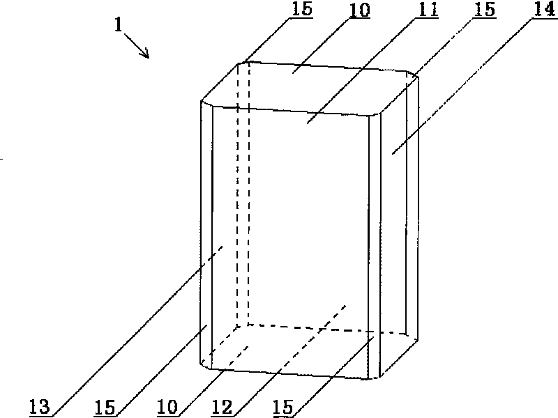
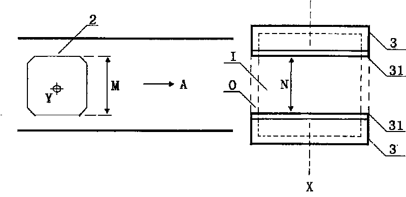
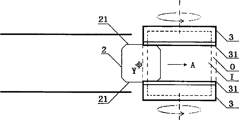
[0038] See Figure 2a To Figure 2i and Figure 3a to Figure 3b , Which is shown as a schematic diagram of the embodiment of the method for grinding surface spheronization of single crystal silicon of the present invention. It should be noted that the drawings are simplified schematic diagrams, and the basic idea of ​​the present invention is only schematically illustrated, so The drawing only shows the components related to the invented single ...


PUM


Abstract

The invention provides a method for the rolling grinding of the ground surface of single crystal silicon. The method comprises the following steps of: oppositely arranging a pair of cup-shaped grinding wheels along transverse axes so as to form an outer-ring grinding space and an inner-ring grinding space between the two cup-shaped grinding wheels; longitudinally arranging the single crystal silicon so as to make the surface to be rolling-ground surface vertical to the transverse axes of the cup-shaped grinding wheels; and when the two cup-shaped grinding wheels rotate around the transverse axes, driving the single crystal silicon to rotate around a longitudinal axis, and transferring the single crystal silicon to the outer-ring grinding space for rolling grinding. Due to the design, the method has the advantages of overcoming the defect existing in the prior art that the round grinding of the single crystal silicon is difficult to control, ensuring the accurate grinding size of the single crystal silicon and improving the quality of the single crystal silicon.

Description

Technical field [0001] The invention relates to a silicon material grinding technology, in particular to a grinding method of single crystal silicon. Background technique [0002] With the depletion of non-renewable energy, the development of renewable energy is gradually being valued. Solar energy, as an unlimited energy and clean energy, has naturally become the top priority in the field of new energy. For this reason, people have invested a lot in this field. Human and material resources have been researched and developed, and at the same time promoted the development of related industries, such as the production and processing of silicon materials as raw materials for solar cells. [0003] Solar cells are made of many solar silicon wafers glued on a metal plate coated with an anti-corrosion conductive layer on the surface with conductive adhesives, and directly convert light energy into electrical energy through photoelectric or photochemical effects. The raw materials for maki...

Claims


Application Information

Patent Timeline
IPC IPC(8): B24B7/22B24B7/17B24B9/16
Inventor 卢建伟
Owner 海宁市日进科技有限公司
Learn More