
Cell pairing and fusion chip

A cell fusion and cell technology, applied in the field of biomedicine, can solve the problems of low specific matching rate, electrical safety hazards, and specific fusion rate not higher than 1%, so as to improve the specific matching rate and reduce manufacturing costs , Improve the effect of cell fusion rate

Active Publication Date: 2010-06-02
JIANGYIN STEMEASY BIOTECH LTD
View PDF0 Cites 6 Cited by
  • Summary
  • Abstract
  • Description
  • Claims
  • Application Information

AI Technical Summary

Problems solved by technology

But it also has the following deficiencies: (1), the specific pairing rate of cells is low, thereby causing the cell fusion rate to generally only reach about 10%; To establish a sufficient electric field strength, the output must be at least hundreds of volts or even thousands of volts, which requires a very high output power of the power supply, which makes the cell electrofusion equipment expensive and has hidden dangers in electrical safety. hampers widespread adoption of this technology
[0006] The third is the chemical method, the inducer adopts polyethylene glycol (PEG), the cost of cell fusion by PEG method is very low, and it is the most widely used, but this fusion technology also has many shortcomings that are difficult to overcome: (1) 1. Poor specific pairing, low fusion efficiency, and the specific fusion rate of different cells is generally not higher than 1%; (2), poor controllability and poor repeatability of the cell fusion process; (3) due to poor specific pairing, the inducer The amount of PEG used is also large, and the inducer has a greater chemical toxic effect on the cells. The larger the amount, the stronger the toxic effect, which is not conducive to the survival and function of fusion cells.

Method used


Image

  • Cell pairing and fusion chip
  • Cell pairing and fusion chip
  • Cell pairing and fusion chip

Examples


Embodiment Construction

[0025] The present invention will be further described below in conjunction with specific drawings and embodiments.

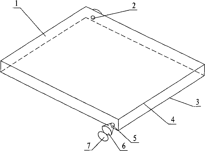
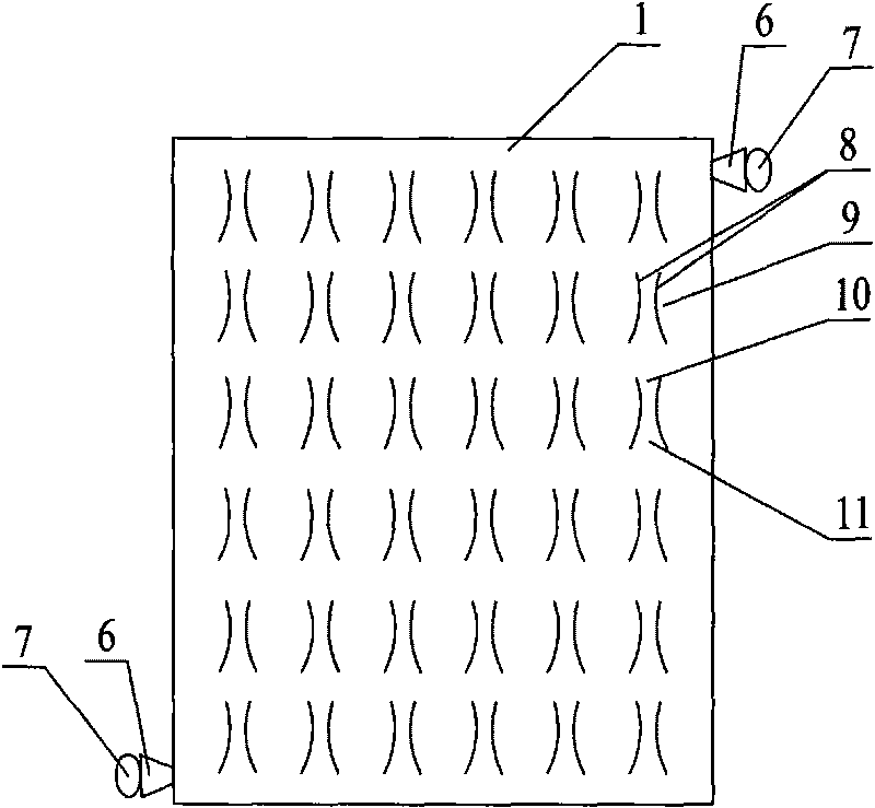
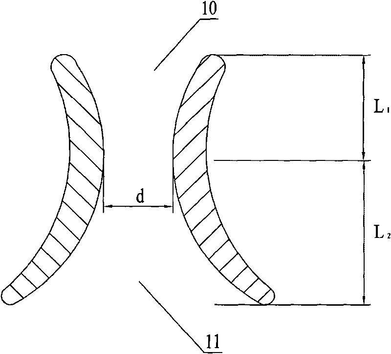
[0026] Such as Figure 1 ~ Figure 3 As shown, the present invention includes a chip body 1, and the chip body 1 is provided with a hollow airtight cell fusion chamber, and a certain number of cell wells 9 are arranged on the bottom plate 3 of the cell fusion chamber to form an array of cell wells 9; the cell wells 9 are composed of two Symmetrical half-moon dikes 8 are formed. The half-moon dikes 8 have a short end and a long end. The convex arc surfaces of the two half-moon dikes 8 face each other, and their short ends form a first opening 10, which can only accommodate a single cell. , their long ends form the second opening 11, the second opening 11 can only accommodate two cells; the bottom of the half-moon-shaped dike 8 is fixed on the bottom plate 3, and the top of the half-moon-shaped dike 8 and the top plate 4 of the cell fusion chamber leave a certain ...


PUM


Abstract

The invention belongs to the biomedicine technical field, relating to a cell pairing and fusion chip. The cell pairing and fusion chip comprises a chip body provided with a hollow and closed cell fusion chamber, wherein a cell trap consisting of two symmetrical semilunar banks is arranged at the bottom plate of the cell fusion chamber. Each bank comprises a short end and a long end; the projecting arc surfaces of the two semilunar banks face to each other, of which the short ends form a first opening, while the long ends form a second opening; the bottom part of the semilunar bank is fixed on the bottom plate; a definite interval exists between the top part of the semilunar bank and the top plate of cell fusion chamber; and the first sampling hole corresponding to the first opening direction of the cell trap and the second sampling hole corresponding to the second opening direction of the cell trap are arranged along the diagonal direction of the cell fusion chamber. The chip with simple and ingenious structure can extremely improve cell paring rate and fusion rate, reduce the chemical poisoning effect of inducer to cell, and be operated easily.

Description

technical field [0001] The invention belongs to the technical field of biomedicine, and relates to a device capable of realizing cell pair fusion, in particular to a cell pair fusion chip. Background technique [0002] Cell fusion refers to the process of combining two or more cells to form one cell under natural conditions or by artificial means (biological, physical, chemical). It has a wide range of application values ​​in genetics, genetics, distant hybrid breeding of animals and plants, immunomedicine, medicine, food, agriculture and other applications. Some advanced technologies in modern biomedicine, such as the production of monoclonal antibodies, cloning of mammals, breeding of microbial strains, mapping of genes and production of anti-tumor vaccines, cell fusion is the most critical step. [0003] Although in the past decades, cell fusion technology has made great progress and achieved world-renowned achievements, there are still many problems, which greatly restr...

Claims


Application Information

Patent Timeline
IPC IPC(8): C12M1/00
CPCC12M47/06
Inventor 陈慧敏徐念沁顾传虎
Owner JIANGYIN STEMEASY BIOTECH LTD
Learn More