Method for preparing polymeric micro-fluidic chip based on hydrogel male mold

A technology of microfluidic chips and hydrogels, which is applied to the photolithographic process of patterned surfaces, welding equipment, manufacturing tools, etc., can solve problems such as polymer microfluidic chips that have not yet been seen, and achieve good application prospects, Ease of demolding and reduction of chip manufacturing costs

Inactive Publication Date: 2013-04-10
FUDAN UNIV
View PDF0 Cites 0 Cited by
  • Summary
  • Abstract
  • Description
  • Claims
  • Application Information

AI Technical Summary

Problems solved by technology

[0004] In related research, we found that various hydrogels have good mechanical strength, especially thermoreversible hydrogels, which will melt into a solution when heated to a certain temperature, and solidify into a gel when cooled to a certain temperature, and can be melted and casted in batches. Replication has a good application prospect in the processing of the male mold of the microfluidic chip, but after reviewing domestic and foreign literature, there is no report of using the hydrogel male mold to process the polymer microfluidic chip.

Method used


Image

  • Method for preparing polymeric micro-fluidic chip based on hydrogel male mold
  • Method for preparing polymeric micro-fluidic chip based on hydrogel male mold
  • Method for preparing polymeric micro-fluidic chip based on hydrogel male mold

Examples


Embodiment 1

[0036] Example 1. Application of gelatin hydrogel positive mold in the preparation of polymethyl methacrylate microfluidic chip

[0037] (1) Design of microfluidic chip

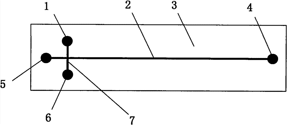
[0038] Adobe Illustrator CS3 software was used to design the microfluidic channel and solution connection hole of the chip, and a high-resolution (3600dpi) laser phototypesetting system was used to print a positive mask on a polyester transparent film. The width of the microfluidic channel on the mask was 50 μm, and the solution The connection hole is a round hole with a diameter of 2mm, in which the microfluidic channel (separation channel 2 and sampling channel 7) and solution holes 1, 4, 5 and 6 (attached figure 1 ) is black and the rest is transparent. The typical design of the microfluidic chip is shown in the appendix figure 1 . The separation microfluidic channel 2 is 65 mm long, and the sampling microfluidic channel 5 is 10 mm long, and the distance from the intersection of microfluidic channels 4 ...

Embodiment 2

[0049] Example 2, the application of agar hydrogel positive mold in the preparation of polydimethylsiloxane and epoxy resin microfluidic chip

[0050] (1) Fabrication of agar hydrogel male mold

[0051] The design of the microfluidic chip and the fabrication of the SU-8 photoresist negative mold 11 are the same as in Example 1.

[0052] After mixing 81.5 grams of water and 5 grams of glycerin (plasticizer) evenly, add 0.5 grams of borax and stir to dissolve it, then disperse 13 agar in the solution, heat to boiling and keep stirring until completely dissolved, and cool to room temperature Elastic gelatin hydrogel impression material.

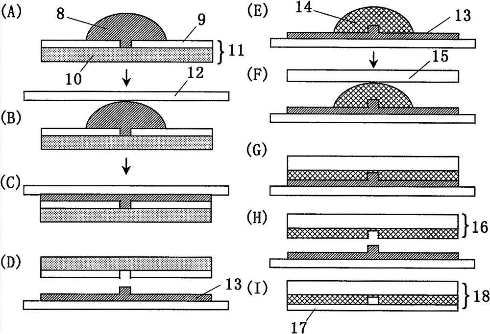
[0053] Before preparing the agar hydrogel positive mold, the agar hydrogel impression material is placed in a water bath at a temperature of 70° C. to melt. Get 1.5 milliliters of molten hydrogel 8 and cast it on the midline of the long side of the photoresist negative mold 11, and then cover the frosted surface of a preheated frosted glass sh...


PUM

PropertyMeasurementUnit
thicknessaaaaaaaaaa
widthaaaaaaaaaa

Abstract

The invention relates to a method for preparing a polymeric micro-fluidic chip based on a hydrogen male mold, which comprises the following steps: transferring a micro-fluidic channel structure of the micro-fluidic chip arranged on a mask into a photoresist layer (9) in an etching way to obtain a photoresist female mold (11); heating and melting agar hydrogel or gelatin hydrogel (8) and pouring the melted hydrogel (8) on the photoresist female mold (11); covering the hair side of a frosted glass plate (12) on the melted hydrogel (8) and pressing the hair side down; after the hydrogel is solidified, separating the solidified hydrogel together with the frosted glass plate (12) from the photoresist female mold (11) to obtain the hydrogel male mold (13); mixing a macromolecular polymer and a curing agent to obtain a casting solution (14); pouring the casting solution (14) on the hydrogel male mold (13) and covering a cover plate (15) over the hydrogel male mold (13) so that a gap between the cover plate (15) and the hydrogel male mold (13) is filled with the casting solution (14); performing mold stripping after the casting solution (14) is solidified at a room temperature to obtain a substrate (16) of the polymeric micro-fluidic chip; and encapsulating the substrate (16) with a cover piece to obtain the finished product (18) of the polymeric micro-fluidic chip. The method can be used for machining the polymeric micro-fluidic chips made from polymethylmethacrylate, dimethyl silicone polymer, epoxy resin and the like.

Description

technical field [0001] The invention belongs to the technical field of microfluidic chips, and in particular relates to a method for preparing a polymer microfluidic chip based on a hydrogel positive mold. Background technique [0002] The microfluidic chip was first proposed by Manz and Widmer[1] in 1990, and it is an important part of the Micro Total Analysis System (μ-TAS). As an emerging micro-separation analysis technology, it has developed into one of the most cutting-edge scientific and technological research fields in the world in just over ten years. This technology involves many disciplines such as analytical chemistry, material science, electronics, micro-electromechanical systems and life sciences, and is a highly integrated technical system. As a new interdisciplinary field, its goal is to realize the overall miniaturization, integration and portability of the chemical analysis system from sample processing to detection by means of micro-electromechanical proce...

Claims


Application Information

Patent Timeline
Patent Type & Authority Patents(China)
IPC IPC(8): B81C99/00B81C3/00
Inventor 陈刚陈挚张鲁雁刘婷
Owner FUDAN UNIV
Why Eureka
Try Eureka