
Method for increasing combustion efficiency of combustion engine

A combustion efficiency, internal combustion engine technology, applied in the direction of internal combustion piston engine, combustion engine, combustion air/combustion-air treatment, etc., can solve the problems of excessive fuel consumption, engine damage, high energy consumption, etc., to reduce the size of the device, improve Combustion efficiency, enhanced activation effect

Inactive Publication Date: 2010-05-05
XI'AN INST OF OPTICS & FINE MECHANICS - CHINESE ACAD OF SCI
View PDF1 Cites 30 Cited by
  • Summary
  • Abstract
  • Description
  • Claims
  • Application Information

AI Technical Summary

Problems solved by technology

For example, the magnetic material fuel economizer, because the product has a strong magnetic field, after a period of use, the iron impurities in the fuel will be adsorbed on the inner pipe wall of the fuel pipe, resulting in blockage of the oil circuit; the far infrared material fuel economizer It is to preheat the fuel. The product is generally wrapped on the outside of the fuel pipe and must have a certain length. This will bring a lot of inconvenience to the installation of the product. In addition, it is easily affected by the external temperature and the fuel-saving effect is unstable; quartz The fuel-saving device of porphyry ceramic technology can only work under the action of external force; when the fuel-saving device of rare earth ore is used near the automobile engine or on the fuel-burning machinery with relatively harsh working environment, it will affect the good performance of the product; the above two turbine devices It is mainly to change the intake air volume of the engine. For EFI cars, if the computer detects the increase of the intake air volume, it will give a signal of more fuel injection at the same time. The power of the car is improved, but the fuel consumption will also follow. There are many kinds of additives, and the principle of action is different. From the perspective of improving combustion efficiency or saving fuel, the effect is generally not very good. It is not easy to save 3% of fuel. On the other hand, although some combustion accelerants Effective, but damaging to the engine itself
[0003] Due to the limitations of various conditions, the above-mentioned products have no obvious effects in saving fuel and reducing exhaust emissions in actual use, and have not fundamentally played a role in energy saving and emission reduction.
In addition, the famous Massachusetts Institute of Technology (MIT) and Los Alamos National Laboratory (Los Alamos National Laboratory-tory) have tried many times to use plasma technology to improve engine combustion efficiency, but the equipment they developed is bulky , high power, high energy consumption, and various limitations, it is still unable to exert practical benefits in energy saving and emission reduction in the automotive industry and other fields
[0004] In the published patent 200810041928 "low temperature plasma pre-oxygenation assisted NH*-SCR purification of diesel engine NO X The inventive device proposed for the direct treatment of exhaust gas in "The System" is too large in size. If it is used to improve the combustion efficiency of internal combustion engines, it will occupy too much extra space in motor vehicles, and the original engine system needs to be greatly modified. cause inconvenience
Secondly, the device described in the patent 200810041928 requires a relatively high-power (1KVA) power supply to maintain its work, so when it is used to improve the combustion efficiency of an internal combustion engine, it not only needs to provide additional power supply equipment, but also consumes too much fuel
Therefore, the device described in the patent 200810041928 cannot be applied to the existing EFI engine system to improve fuel combustion conditions to improve combustion efficiency

Method used


Image

  • Method for increasing combustion efficiency of combustion engine
  • Method for increasing combustion efficiency of combustion engine
  • Method for increasing combustion efficiency of combustion engine

Examples


Embodiment Construction

[0094] The present invention will be described in detail below in conjunction with the accompanying drawings.

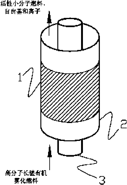
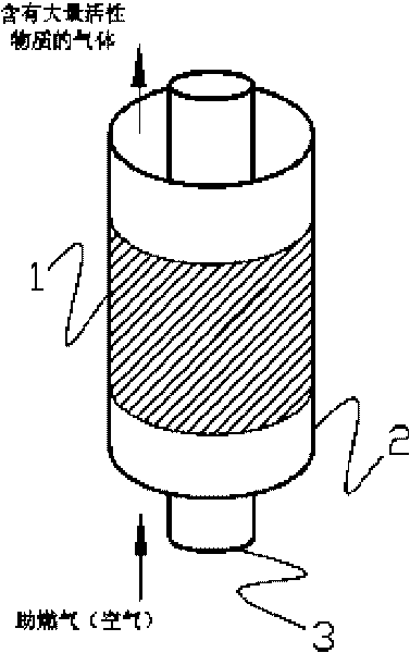
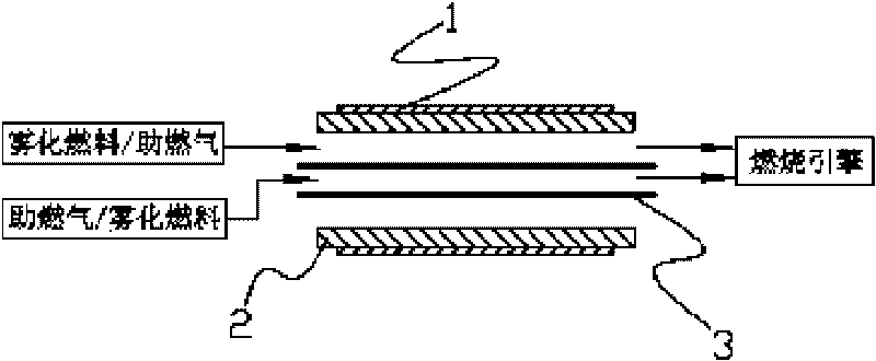
[0095] Such as Figure 1a , Figure 1b As shown, the main structure of the plasma generator (miniature plasma generator unit) proposed by the present invention is tube-tube type, and the tube-tube type structure can ensure smooth flow of air and obtain relatively uniform plasma; secondly, the adoption cost is low, Metal materials (stainless steel, copper, aluminum foil or platinum, etc.) that have little effect on the efficiency are used as the internal and external electrodes of the discharge; again, insulating materials with high withstand voltage and strong corrosion resistance (corundum, ceramics, mica, etc.) are selected as the tubular discharge medium . The tubular inner electrode 3 is located in the center of the tubular discharge medium 2, and its outer surface is a multi-turn convex platform or threaded structure. The outer electrode 1 (metal mesh or metal...


PUM

PropertyMeasurementUnit
Thicknessaaaaaaaaaa
Outer radiusaaaaaaaaaa
Thicknessaaaaaaaaaa

Abstract

The invention provides a new method for increasing combustion efficiency of a combustion engine; based on non equilibrium plasma technology, a non equilibrium plasma generator with low power is designed and applied, has small volume, can be widely applied to such as fuel power equipment such as automobiles, airplanes and the like and really realizes the combustion efficiency increase of the fuel equipment and exhaust emission reduction. The non equilibrium plasma generator provided by the invention is applied for carrying out controllable dielectric barrier discharge so as to activate fuel or combustion-supporting fuel, thus fundamentally improving combustion situation of the fuel, causing the fuel to fully and effectively burn and simultaneously achieving the effect of energy saving and emission reduction.

Description

technical field [0001] The invention relates to a method for improving the combustion efficiency of an internal combustion engine, which is specifically applied to the improvement of the combustion efficiency of fuel oil equipment and the reduction of tail gas emissions. Background technique [0002] The methods currently on the market to improve engine combustion efficiency are mainly realized by adding fuel-saving devices respectively. Fuel-saving devices generally include the following products: magnetic material fuel-saving device, far-infrared material fuel-saving device, quartz porphyry ceramic technology fuel-saving device, rare earth ore technology fuel-saving device, fixed blade turbine fuel-saving device, rotatable Turbo fuel-saving device, and fuel additives, etc. During the use of these products, due to the reasons of the technology itself, there are more or less problems or deficiencies. For example, the magnetic material fuel economizer, because the product h...

Claims


Application Information

Patent Timeline
IPC IPC(8): F02M27/04
CPCY02T10/126Y02T10/12
Inventor 段忆翔赵卫汤洁
Owner XI'AN INST OF OPTICS & FINE MECHANICS - CHINESE ACAD OF SCI
Learn More