Servo system for linear motor
A linear motor and servo system technology, applied in the field of linear motor servo system and linear motor, can solve the problems of large gap, limited test data, lack of comparative data and production experience, etc., and achieve the effect of high processing speed
- Summary
- Abstract
- Description
- Claims
- Application Information
AI Technical Summary
Problems solved by technology
Method used
Image
Examples
Embodiment 1
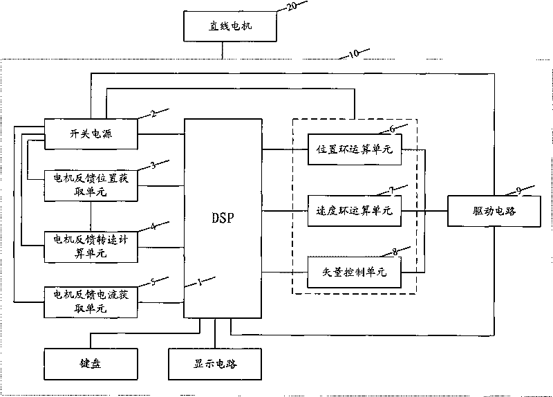
[0037] see figure 1 , the present invention discloses a linear motor servo system, including a linear motor 20 and a linear motor driver 10 . Such as figure 1As shown, the linear motor driver 10 includes a digital signal processor 1, a switching power supply 2, a motor feedback position acquisition unit 3, a motor feedback speed calculation unit 4, a motor feedback current acquisition unit 5, a position loop calculation unit 6, and a speed loop calculation unit 7 , a vector control unit 8, and a drive circuit 9. The digital signal processor 1 and the switching power supply 2 are respectively connected with other units.
[0038] 【Digital Signal Processor DSP】
[0039] The digital signal processor DSP is used to control the position loop, speed change circuit and current loop of the linear motor. The interior of the DSP chip adopts the Harvard structure that separates the program and data, has a special hardware multiplier, widely uses pipeline operations, and provides speci...
Embodiment 2
[0089] In this embodiment, in order to read the position and speed of the mover, HEIDENHAIN incremental grating scale LS1378C is installed on the stator side of the linear motor. The signal period is 1um, that is, the mover stroke of 1mm can feedback 1000 pulses. The pole pitch of the linear motor is 32mm, and one electric distance corresponds to 32000 pulses.
[0090] In order to be able to read the initial stop state of the mover in the power-on state, a Hall device relatively fixed to the mechanical position of the mover coil is installed on the mover side.
[0091] There are generally four speed detection methods: M method, T method, M / T method and variable M / T method, among which the last detection method has the highest accuracy.
[0092] The variable M / T method not only measures the pulse M1 of the encoder and the high-frequency clock pulse M2, but also the measurement time TC is also changing. The purpose is to always keep TC as the sum of the complete encoder pulse si...
Embodiment 3
[0099] see Figure 3-Figure 6 The difference between this embodiment and the above embodiments is that in this embodiment, the system of the present invention includes a parameter management module. Servo driver parameters are divided into user parameters (Table 1 is the user parameter table of this embodiment), system parameters and development parameters, and different levels are managed through passwords. In addition to observing and modifying parameters of this level, high-level passwords can also perform the same operations on low-level parameters.
[0100] Preface
No
name
Applicable party
Mode
parameter range
Factory default
unit
0
P, S
0~9999
315
1
Drive model
P, S
0~19
0*
2
Software version (read only)
P, S
*
*
3
initial display state
P, S
0~20
0
4
control mode se...
PUM
 Abstract
Description
Claims
Application Information
 - R&D
- Intellectual Property
- Life Sciences
- Materials
- Tech Scout
- Unparalleled Data Quality
- Higher Quality Content
- 60% Fewer Hallucinations
Browse by: Latest US Patents, China's latest patents, Technical Efficacy Thesaurus, Application Domain, Technology Topic, Popular Technical Reports.
© 2025 PatSnap. All rights reserved.Legal|Privacy policy|Modern Slavery Act Transparency Statement|Sitemap|About US| Contact US: help@patsnap.com


