
Evaporator for mobile anhydrous ammonia production, and method for manufacturing such an evaporator

A technology of evaporation device and evaporator, which is applied in evaporation device, boiling device, exhaust device, etc., can solve the problems of blockage of evaporator unit and achieve the effect of effective evaporation

Inactive Publication Date: 2010-03-24
EMITEC EMISSIONSTECHNIK
View PDF0 Cites 3 Cited by
  • Summary
  • Abstract
  • Description
  • Claims
  • Application Information

AI Technical Summary

Problems solved by technology

If complete evaporation is not achieved, intermediate products may be formed which may cause blockage of the evaporator unit

Method used


Image

  • Evaporator for mobile anhydrous ammonia production, and method for manufacturing such an evaporator
  • Evaporator for mobile anhydrous ammonia production, and method for manufacturing such an evaporator
  • Evaporator for mobile anhydrous ammonia production, and method for manufacturing such an evaporator

Examples


Embodiment Construction

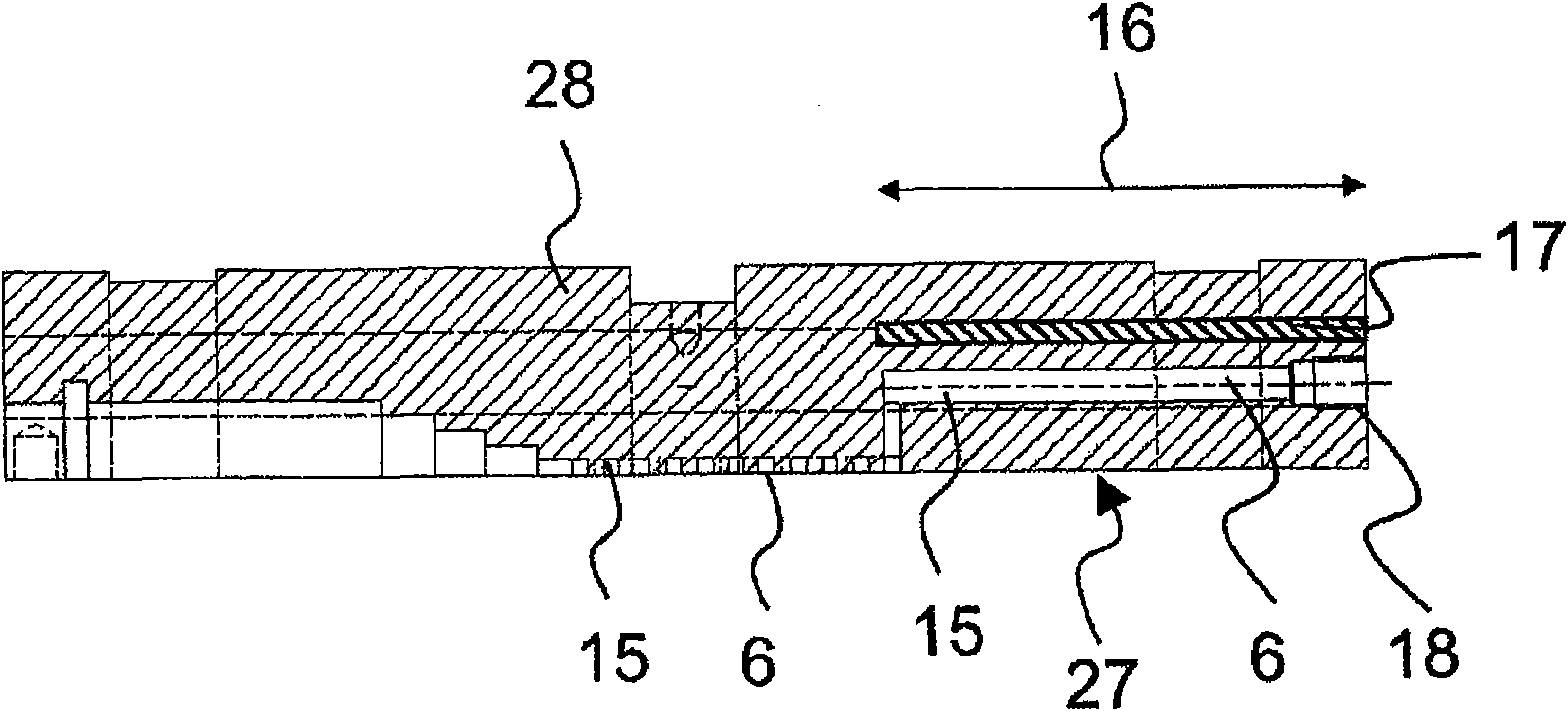
[0092] figure 1 The structure of a particularly preferred variant embodiment of the evaporation device 1 is schematically shown, the main body 2 used here being shown "open" for the sake of clarity. according to figure 1 , the main body 2 comprises a first part 28 and a second part 29 which are connected together by their common interface 27 in order to make the evaporation device 1 work. In this two-piece construction of the main body 2 , the first part 28 and the second part 29 each have two receptacles 30 , each for receiving a heating element 5 positioned at the longitudinal axis 39 of the main body 2 . extends across the entire length in the direction of . Also shown in the right-hand area are electrical connections for a heating element formed as a PTC resistor (PTC: positive temperature coefficient or so-called Kaltleiter). Starting from the interface 27 , the upper region of the reactor chamber 21 is formed in the second part 29 . Only the outlet portion 19 of the ...


PUM

PropertyMeasurementUnit
mean roughnessaaaaaaaaaa
surface roughnessaaaaaaaaaa

Abstract

Disclosed is an evaporator (1) for ammonia to be used in mobile emission systems. Said evaporator (1) comprises a base (2) encompassing at least one supply pipe (3) and at least one discharge pipe (4). At least one heating element (5) and at least one duct (6) for connecting the supply pipe (3) to the discharge pipe (4) are arranged within the base (2). The at least one heating element (5) is in heat-conducting contact with an evaporation section (7) of the at least one duct (6), while the at least one duct (6) has a serpentine shape (8) in said evaporation section (7).

Description

technical field [0001] The invention relates to a vaporization device and a method for producing the same, said vaporization device comprising a body with at least one input and at least one output, in which body at least one heating element is arranged and at least one channel for connecting the input and the output. Such an evaporating device is used in particular to heat or superheat the aqueous urea solution so that ammonia is ultimately formed in this way, which can be supplied to the exhaust system of the motor vehicle to convert harmful substances in the exhaust gas. Background technique [0002] In particular in diesel internal combustion engines, it has proven effective to add aqueous urea solutions directly to the exhaust gas produced by the internal combustion engine or to add ammonia after external hydrolysis. In the known process, hydrolysis catalysts are used in which ammonia is obtained from urea. An aqueous urea solution is added upstream of the hydrolysis ...

Claims


Application Information

Patent Timeline
Patent Type & Authority Applications(China)
IPC IPC(8): B01B1/00
CPCC01C1/086B01B1/005Y10T29/49988B01B1/00F01N3/10F01N3/20
Inventor P·希尔特M·布鲁格尔T·黑里希R·布吕科C·沃斯曼
Owner EMITEC EMISSIONSTECHNIK
Learn More