
Display device and manufacturing method thereof

A technology for display devices and manufacturing methods, applied in instruments, nonlinear optics, optics, etc., can solve the problems of no thinning, high energy consumption, increased volume and thickness of the backlight source, etc., and achieves fast dynamic response speed and transmittance. high rate effect

Active Publication Date: 2010-03-03
K TRONICS (SUZHOU) TECH CO LTD +1
View PDF0 Cites 2 Cited by
  • Summary
  • Abstract
  • Description
  • Claims
  • Application Information

AI Technical Summary

Problems solved by technology

The optical anisotropy of liquid crystal molecules makes the display device have viewing angle dependence; because the liquid crystal display has to control the transmittance of visible light multiple times on all optical paths, the optical transmittance is very low and the energy consumption is large; As the size of the display increases, the volume and thickness of the backlight source also increase significantly, and it does not have the characteristics of thinning; due to the many limitations of the liquid crystal material molecules in their viscosity and mechanical and electromagnetic properties, the response speed of the display device is especially high. Slower in dynamic response

Method used


Image

  • Display device and manufacturing method thereof
  • Display device and manufacturing method thereof
  • Display device and manufacturing method thereof

Examples


no. 1 example

[0061] The first embodiment of the manufacturing method of the display device of the present invention includes:

[0062] A color filter polymer with a magnetized ferromagnetic light-transmitting substance is attached on one surface of a glass substrate; a pixel electrode and its control unit are formed on one surface of a total internal reflection substrate; A spacer array is arranged around the color filter polymer; the glass substrate and the total internal reflection substrate are boxed.

[0063] Specifically, color filter polymers of three primary colors are pasted on the glass substrate, and their functions are the same as the color filter films in liquid crystal display devices, and are the necessary basis for producing color pictures. The substance is an organic polymer and therefore stretchable. The color filter polymer is embedded with a magnetized ferromagnetic light-transmitting material. At present, the magnetized ferromagnetic light-transmitting material formed ...

no. 3 example

[0076] The third embodiment of the manufacturing method of the display device of the present invention includes:

[0077] The pixel electrode and its control unit are formed on the glass substrate, and the color filter polymer embedded with the magnetized ferromagnetic light-transmitting substance is attached to the glass substrate on which the pixel electrode and its control unit have been formed; A spacer array is arranged around a color filter polymer; a glass substrate and a total internal reflection substrate are boxed.

[0078] The step of arranging the spacer array around the glass substrate on which the color filter polymer is attached can also adopt the method of arranging the spacer array at a corresponding position on a surface of the total internal reflection substrate.

[0079] The difference between this embodiment and the second embodiment of the method for manufacturing a display device of the present invention is that in this embodiment, the pixel electrode an...

no. 4 example

[0082] The fourth embodiment of the manufacturing method of the display device of the present invention includes:

[0083] The color filter polymer embedded with the magnetized ferromagnetic light-transmitting substance is attached to the glass substrate; the pixel electrode and its control unit are formed on the surface of the color filter polymer; the color filter polymer is attached to the glass substrate A spacer array is arranged around the object; the glass substrate and the total internal reflection substrate are boxed.

[0084] The step of arranging the spacer array around the glass substrate on which the color filter polymer is attached can also adopt the method of arranging the spacer array at a corresponding position on a surface of the total internal reflection substrate.

[0085] In this embodiment, the color filter polymer embedded with the magnetized ferromagnetic light-transmitting substance is attached on the glass substrate, and then the pixel electrode and i...


PUM


Abstract

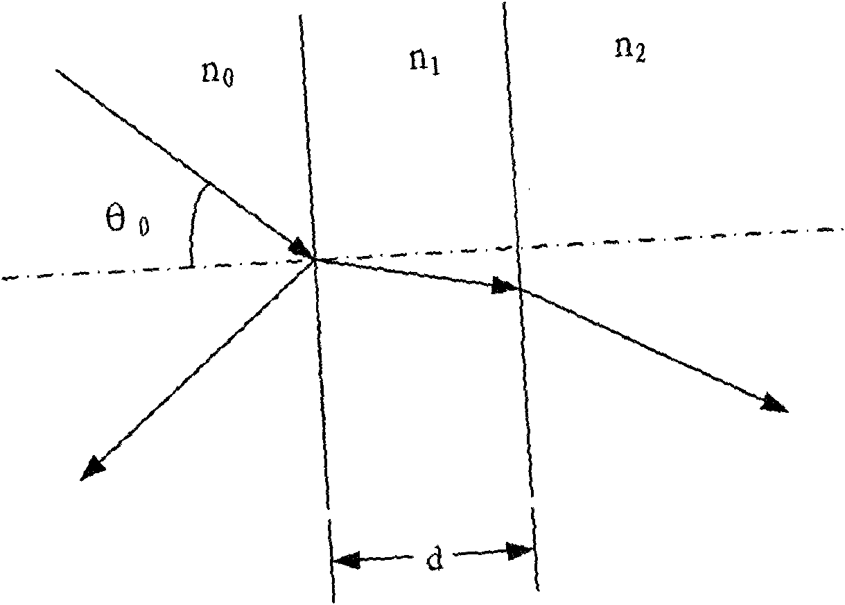
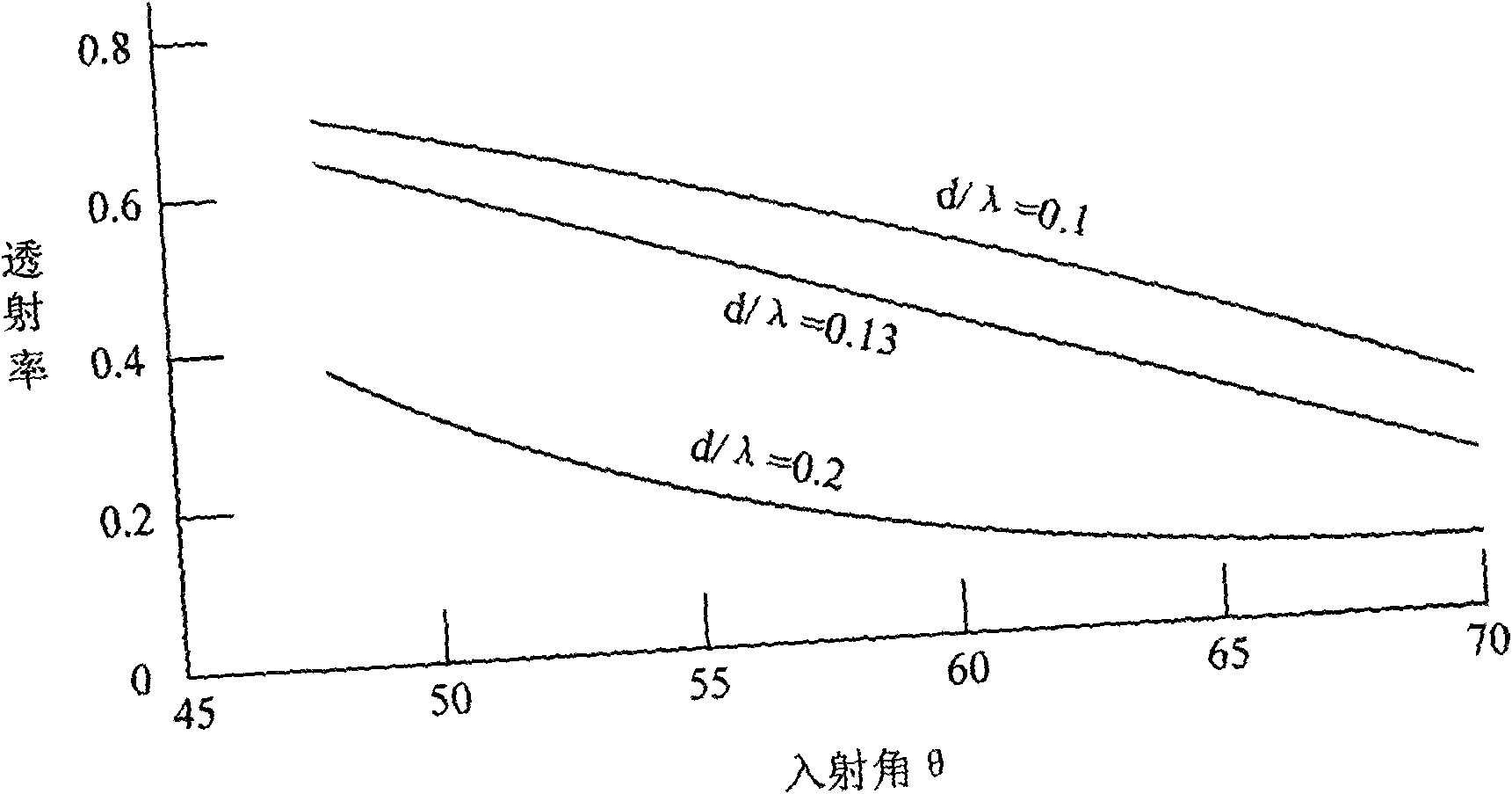
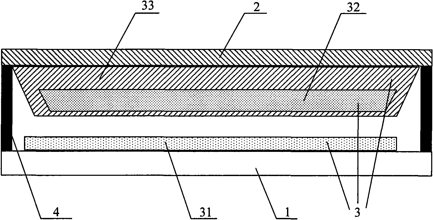
The invention discloses a display device and a manufacturing method of the display device. The display device comprises a total internal reflection substrate, a glass substrate and a light ray transmission device, wherein the total internal reflection substrate is used for transmitting light rays to the light ray transmission device during frustrated total internal reflection; the glass substrateis used for assembling with the total internal reflection substrate to generate a light source transmission space and transmitting visible light; and the light ray transmission device comprises a pixel electrode and a control unit of the pixel electrode, a magnetized ferromagnetic non-light tight material and a color optical filtering polymer combined with the magnetized ferromagnetic non-light tight material, wherein the color optical filtering polymer is arranged on the glass substrate, and the light ray transmission device is used for vibrating the color optical filtering polymer in the light source transmission space through magnetic effect when the pixel electrode is charged to generate an alternative electric field, and transmits the visible light in light rays out of the glass substrate when the light ray transmission device is close to the total internal reflection substrate. The display device has the advantages of visible full viewing angle, higher transmittance of the lightrays, energy and power conservation, lightness and thinness portability, and quick dynamic response speed.

Description

technical field [0001] The invention relates to the technical field of manufacturing liquid crystal displays, in particular to a display device and a method for manufacturing the display device. Background technique [0002] With the continuous improvement of liquid crystal display manufacturing technology and the continuous reduction of costs, liquid crystal displays have been widely used. [0003] The basic principle of liquid crystal display is to use the anisotropy of optical transmission of liquid crystal material molecules in the electric field to control the transmission of light, so as to achieve the effect of picture display. Specifically, the main components of a thin film transistor (hereinafter referred to as TFT) type liquid crystal display include fluorescent tubes, light guide plates, polarizers, filter plates, glass substrates, alignment films, liquid crystal materials, and TFTs. First of all, the liquid crystal display must first use the backlight, that is,...

Claims


Application Information

Patent Timeline
IPC IPC(8): G02F1/01
Inventor 张原峰
Owner K TRONICS (SUZHOU) TECH CO LTD
Learn More