
Flexible composite beam electric heating microdriver based on U+V shape

A technology of micro-driver and composite beam, which is applied in the direction of thermal effect motor, optical waveguide coupling, piezoelectric effect/electrostrictive or magnetostrictive motor, etc., which can solve the problem of low energy utilization rate, poor bonding force, thermal energy, etc. Large loss and other problems, to achieve the effect of improving energy utilization, preventing device failure, and easy process realization

Inactive Publication Date: 2010-01-06
SHANGHAI JIAO TONG UNIV
View PDF0 Cites 20 Cited by
  • Summary
  • Abstract
  • Description
  • Claims
  • Application Information

AI Technical Summary

Problems solved by technology

However, this out-of-plane driven electrothermal driver has the following significant disadvantages: 1. The residual stress in the process makes the end of the structure warp when it is finally released and suspended, which cannot keep the cantilever structure straight; 2. Due to There is a large difference in thermal expansion coefficient between the double-layer membrane materials. When the driving displacement is generated, due to the thermal mismatch between the two, the bonding force between them is poor and it is easy to fall off; 3. Because only Using the layer with a larger thermal expansion coefficient as the electrothermal driving layer, only a part of the heat generated by it is conducted to the double-layer structure, and the heat energy is dissipated greatly, so the energy utilization rate is low
Under normal circumstances, for electrothermal devices, the heating process is much greater than the cooling process. Obviously, this design has not avoided the disadvantages, so the driver response is very low, and the driving voltage is high, which is not compatible with the standard process of integrated circuits.

Method used


Image

  • Flexible composite beam electric heating microdriver based on U+V shape
  • Flexible composite beam electric heating microdriver based on U+V shape
  • Flexible composite beam electric heating microdriver based on U+V shape

Examples


Embodiment Construction

[0025] The embodiments of the present invention are described in detail below. This embodiment is implemented on the premise of the technical solution of the present invention, and detailed implementation methods and specific operating procedures are provided, but the protection scope of the present invention is not limited to the following implementation example.

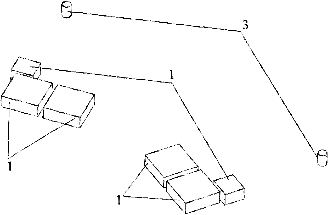
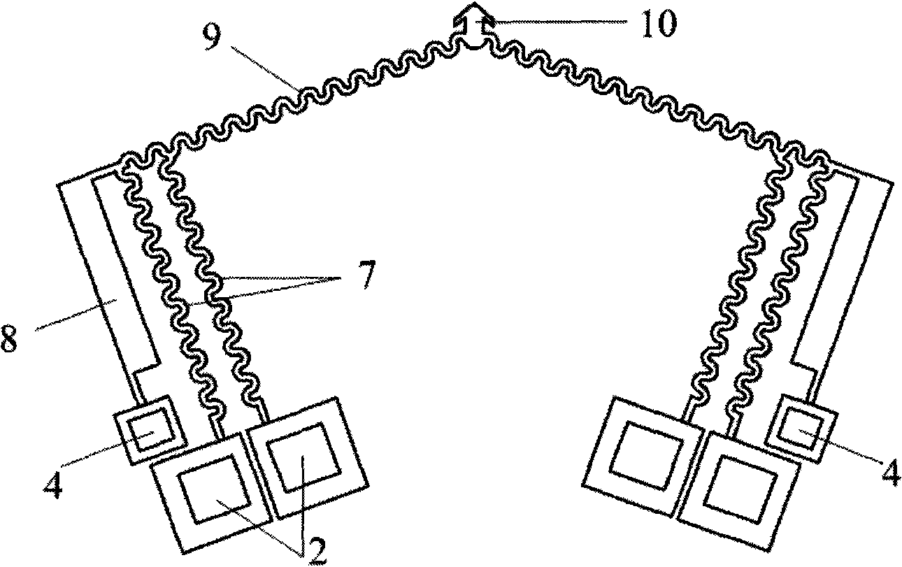
[0026] Such as Figure 1 to Figure 4 As shown, embodiment 1 includes: U-shaped beam base 1, U-shaped beam electrode 2, V-shaped beam base 3, V-shaped beam electrode 4, U-shaped double heating arm composite beam electrothermal driver 5 and V-shaped composite beam electrothermal driver The driver 6, wherein: two sets of U-shaped beam bases 1 and V-shaped beam bases 3 of the same structure are respectively located on the substrate, U-shaped beam electrodes 2 are located on the U-shaped beam base 1, and V-shaped beam electrodes 4 are located on the On the V-shaped beam base 3, the U-shaped double-arm composite beam el...


PUM


Abstract

The invention relates to a flexible composite beam electric heating microdriver based on a U+V shape, which belongs to the technical field of microelectromechanical systems. The flexible composite beam electric heating microdriver based on a U+V shape comprises a U-shaped beam base, a U-shaped beam pole, a V-shaped beam base, a V-shaped beam pole, a U-shaped double-hot arm composite beam electric heating driver and a V-shaped composite beam electric heating driver, wherein the U-shaped double-hot arm composite beam electric heating driver comprises a U-shaped double-hot arm metal resistance wire, a U-shaped metal cold arm, a U-shaped double-hot arm polymer drive layer and a U-shaped cold arm polymer layer; and the V-shaped composite beam electric heating driver comprises a V-shaped metal resistance wire, a metal contact point and a V-shaped polymer drive layer. The U-shaped double-hot arm metal resistance wire, the U-shaped metal cold arm and the V-shaped metal resistance wire are completely coated by the U-shaped double-hot arm polymer drive layer, the U-shaped cold arm polymer layer and the V-shaped polymer drive layer to form a polymer-metal-polymer sandwich structure. The electric heating microdriver has larger drive displacement, higher drive rigidity, low power consumption and high energy utilization ratio.

Description

technical field [0001] The invention relates to a device in the technical field of micro-electro-mechanical systems, in particular to a U+V-type flexible composite beam electrothermal micro-driver. Background technique [0002] The micro-actuator is the key component to realize the micro-drive function in the micro-electromechanical system (MEMS). The indicators such as the size of the driving displacement / force, the driving efficiency and the reliability of the action determine the success or failure of the system. It has become a research topic at home and abroad in recent years. one of the hotspots. According to different energy supply methods, micro-actuators are generally divided into electrostatic type, electromagnetic type, piezoelectric type, electric heating type, etc. Electrostatic and electromagnetic microactuators must operate at resonance or high voltage to achieve large displacements, and they also generate very small forces. In comparison, piezoelectric and ...

Claims


Application Information

Patent Timeline
IPC IPC(8): H02N10/00B81B7/02
Inventor 张丛春吴义伯王娟张小波王亚攀丁桂甫
Owner SHANGHAI JIAO TONG UNIV
Learn More