
Test method of chip junction temperature in LED illumination lamps

A technology of LED lamps and LED chips, which is applied in the directions of radiation pyrometry, measuring device, optical radiation measurement, etc., can solve the problems of large gap width error, measurement value movement, high cost, etc., and meet the requirements of junction temperature measurement accuracy and determination The effect of improving accuracy and overcoming the large error of luminous peak position

Inactive Publication Date: 2009-12-30
SHANGHAI INST OF TECHNICAL PHYSICS - CHINESE ACAD OF SCI
View PDF0 Cites 24 Cited by
  • Summary
  • Abstract
  • Description
  • Claims
  • Application Information

AI Technical Summary

Problems solved by technology

At present, there are usually several methods for measuring LED junction temperature: 1. Forward voltage method: using the temperature effect of LED electrical transport, under the condition of constant current, the linear relationship between forward voltage and junction temperature is obtained; 2. Pin method: it uses the pin temperature of the LED to obtain the junction temperature through the power dissipation and thermal resistance coefficient; 3, the blue-white ratio method: it is a non-contact measurement method that uses the white LED electroluminescent spectrum The power ratio of blue light to white light is used to measure the junction temperature; 4. Infrared camera method: it is a commonly used method to measure the junction temperature distribution, but its cost is high, the speed is slow, and the device is in an unpackaged or unsealed state
However, these methods are limited to the measurement of single-tube LED devices. For the detection of dozens or even hundreds of single-tube series-parallel LED lamp groups, due to the complexity brought about by the mutual crosstalk formed electrically, all electrical The method is difficult to apply; and the infrared method is no longer simply exposed outside the LED chip after packaging, so the infrared rays radiated from the chip are blocked by the packaging material, making the infrared non-contact measurement method invalid; The white ratio method is most suitable for the measurement of lamps, but its accuracy is only ±2 degrees in the best results reported in the literature, and requires prior knowledge of the product. The movement of the blue light emission wavelength will cause a large movement of the measured value. It brings great difficulties to the calibration problem in the measurement method, so it is difficult to be practically applied
We determine the junction temperature of LED chips in LED lamps by using the law of the band gap of LED materials changing with temperature. At present, this method can only set the junction temperature to an accuracy of more than 10 degrees, which is mainly hindered by determining the junction temperature from the luminescence spectrum. The error of the forbidden band width of the material in the region is relatively large, so far there is no effective method to measure the accuracy of the junction temperature of the chip in the LED lighting fixture to within 1 degree

Method used


Image

  • Test method of chip junction temperature in LED illumination lamps
  • Test method of chip junction temperature in LED illumination lamps
  • Test method of chip junction temperature in LED illumination lamps

Examples


Embodiment Construction

[0024] The present invention will be further described in detail below through the embodiments and accompanying drawings.

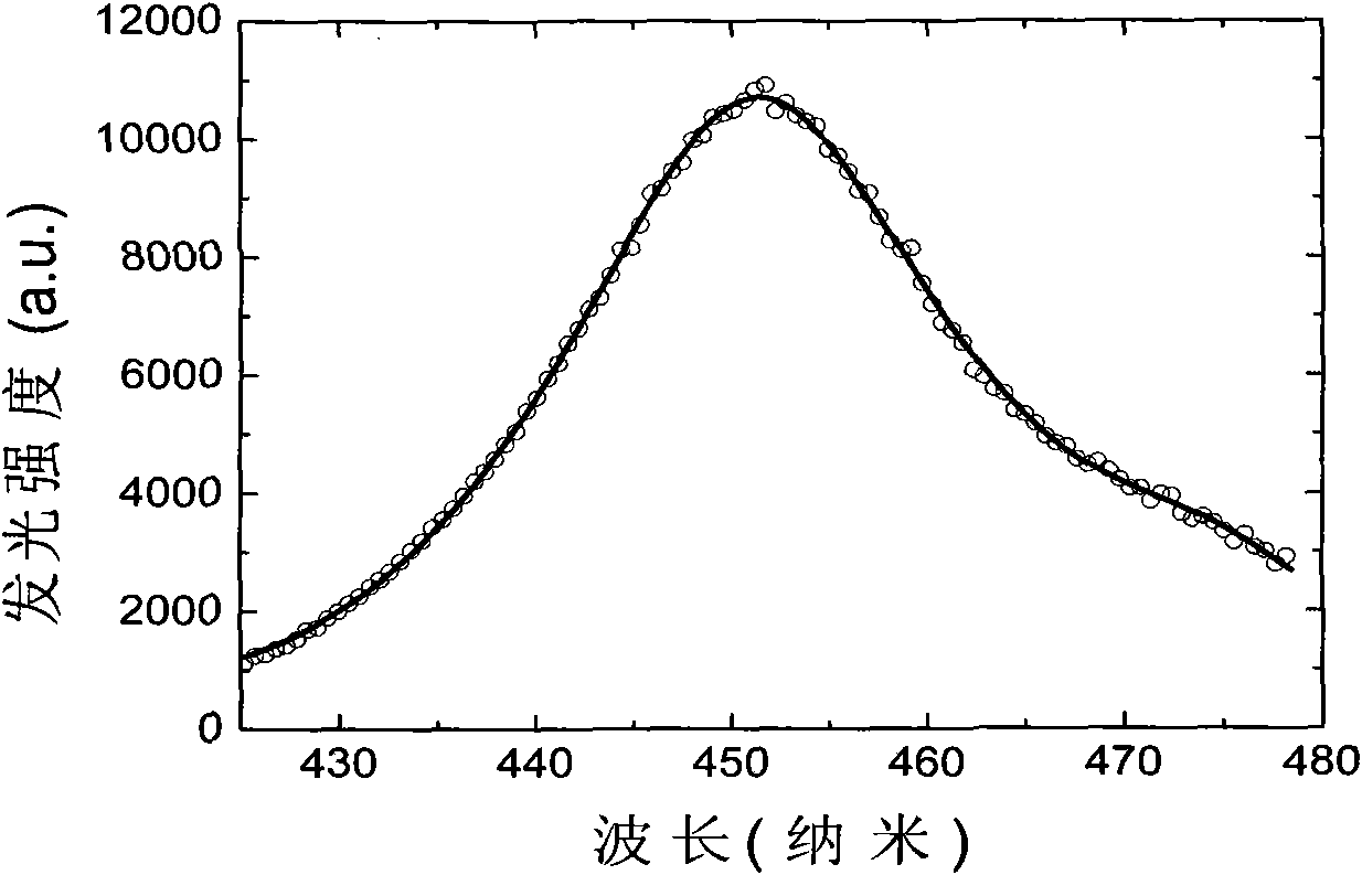
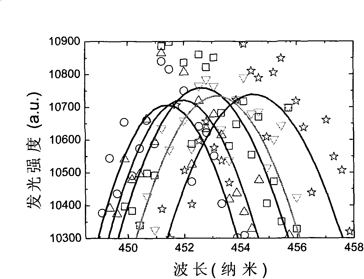
[0025] 1. Connect the LED lamp to be tested to emit light. The rated power of the LED lamp is 100 watts, and the rated voltage is 32~34 volts. In this example, a 33V regulated voltage source is used for power supply. The duty cycle of the voltage source is 1% and DC. model. The light emitted by the lamp is directly introduced into the spectrometer through the optical fiber. The application of spectrometer can get LED lamps such as Figure 4 The spectrum shown in the inset is very similar to the spectrum obtained by the two power supply modes of 1% and DC, but there is a small shift in the spectral peak at about 450 nm, which is due to the junction temperature of the two power supply modes Because of the difference, the present invention is to determine the movement amount with high precision.

[0026] 2. Under the action of pulse power supply with low ...


PUM


Abstract

The invention discloses a method for testing chip junction temperature in LED illumination lamps. The invention determines LED chip junction temperature in an LED illumination lamp according to the law that LED material forbidden band width changes along with temperature, comprising three steps: (1) switching on pulse voltage with very low duty ratio, thud directly obtaining the illuminating peak position of the LED chip at the temperature; (2) measuring the illuminating peak position of the LED lamp under normal operating condition, contrasting the illuminating peak positions to obtain the drifting volume of the illuminating peak positions, namely the difference of the two, and using the drifting volume of wave length to measure the temperature difference of the two; and (3) measuring under very low pulse voltage in step 1 with temperature being room temperature, and judging the temperature of the LED chip in the LED lamp under the condition according to the room temperature and the temperature difference of the two. The invention can represent the actual temperature of the LED chip in the LED lamp under different conditions within the error range of plus or minus 0.6 degree, thus being beneficial for the performance representation and optimized research of the LED lamp.

Description

technical field [0001] The invention relates to a detection technology of a semiconductor light-emitting diode (LED), in particular to a detection method of a chip junction temperature in an LED lighting fixture. Background technique [0002] Energy-saving lamps are an international development trend. China has taken the lead in the application of LED energy-saving lamps in the world. It was embodied in the Beijing Olympics and will be further developed in the Shanghai World Expo. In this rapidly developing field, the effective detection technology of the LED chip junction temperature in LED lamps, an important technical parameter that determines the reliability of LED energy-saving lamps, has been far behind. The necessary guarantee for rapid application development. [0003] LED uses a solid semiconductor chip as a light-emitting material. When a forward voltage is applied to both ends, the carriers in the semiconductor recombine to cause photon emission to produce visibl...

Claims


Application Information

Patent Timeline
Patent Type & Authority Applications(China)
IPC IPC(8): G01J5/60G01R31/26
Inventor 陆卫何素明张波郭少令胡伟达李天信李宁陈平平李志锋陈效双
Owner SHANGHAI INST OF TECHNICAL PHYSICS - CHINESE ACAD OF SCI
Learn More