Method for protecting contact point of relay in high-power circuit and protection circuit
A relay contact and protection circuit technology, applied in emergency protection circuit devices, relays, circuits, etc., can solve problems such as relay contact burnout, relay failure, user personal or property safety hazards, etc., to protect relay contacts, Avoid the effect of high current shock
- Summary
- Abstract
- Description
- Claims
- Application Information
AI Technical Summary
Problems solved by technology
Method used
Image
Examples
Embodiment 1
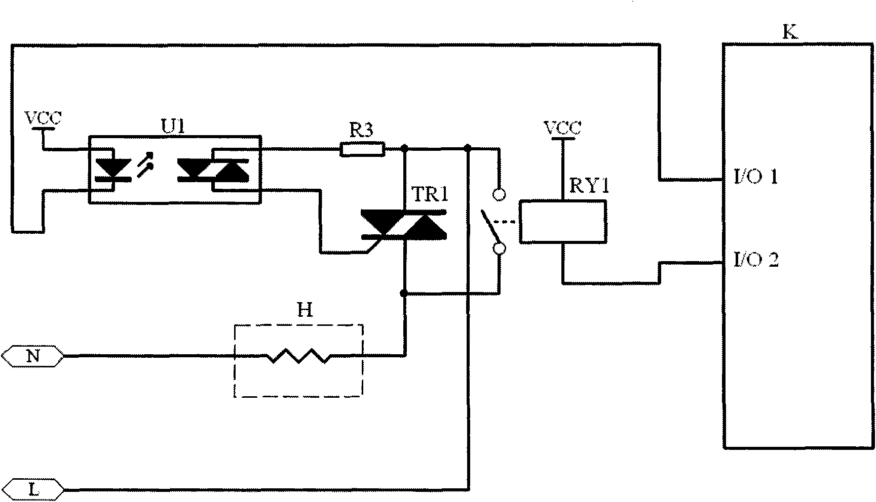
[0018] figure 1 A first specific implementation manner of the protection circuit of the present invention is shown. This circuit is a protection circuit for an oven, and the high-power load in this circuit is the heating coil H.
[0019] The protection circuit includes a third resistor R3, an optocoupler U1, a thyristor TR1, a relay RY1, and a controller K; The T2 terminal of the silicon TR1 is connected to the phase line L of the AC power supply, and the T1 terminal of the thyristor TR1 is connected to the neutral line N of the AC power supply through the heating coil H; the G pole of the thyristor TR1 is connected to the first output terminal of the optocoupler U1 , the second output end of the optocoupler U1 is connected to one end of the third resistor R3, the other end of the third resistor R3 is connected to the T2 end of the thyristor TR1, the control A pole of the optocoupler U1 is connected to the DC power supply, and the control pole of the optocoupler U1 The K pol...
Embodiment 2
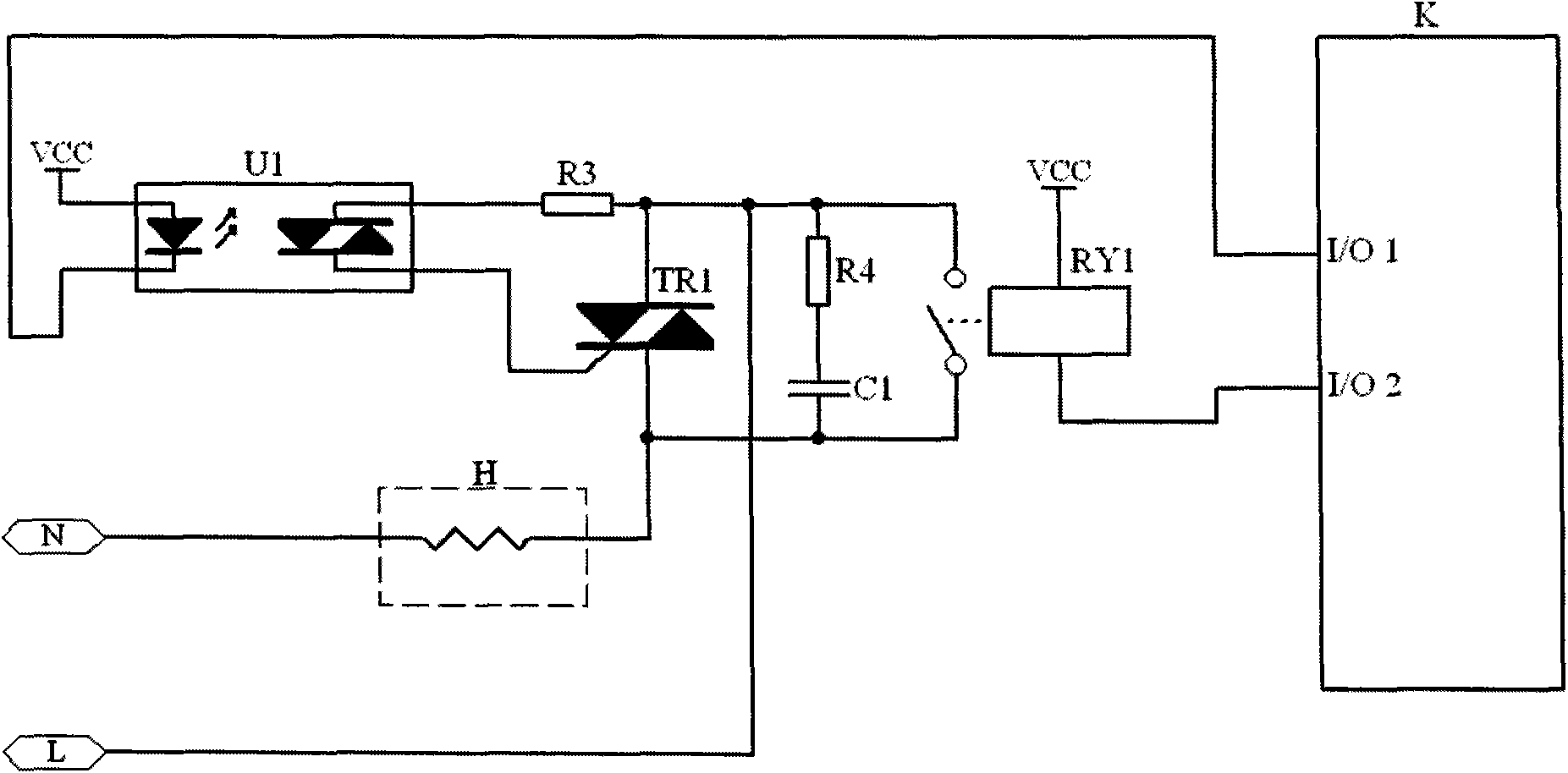
[0025] figure 2 A second specific implementation manner of the protection circuit of the present invention is shown.
[0026] On the basis of Embodiment 1, the protection circuit also includes an RC absorbing circuit composed of a fourth resistor R4 and a capacitor C1, one end of the fourth resistor R4 is connected to the T2 end of the thyristor TR1, and the other end is connected to one end of the capacitor C1. The other end of the capacitor C1 is connected to the T1 end of the thyristor TR1. In this way, it is also possible to provide protection for the contacts of the relay when the heating coil H is out of operation.
[0027] The protection circuit protects the relay contacts as follows: before the relay RY1 is closed, firstly control the thyristor TR1 for soft start processing to preheat the heating coil H, and avoid a large current impact on the relay RY1 contacts. Before disconnecting the relay RY1, first turn on the thyristor TR1 and delay the shutdown, and use the ...
Embodiment 3
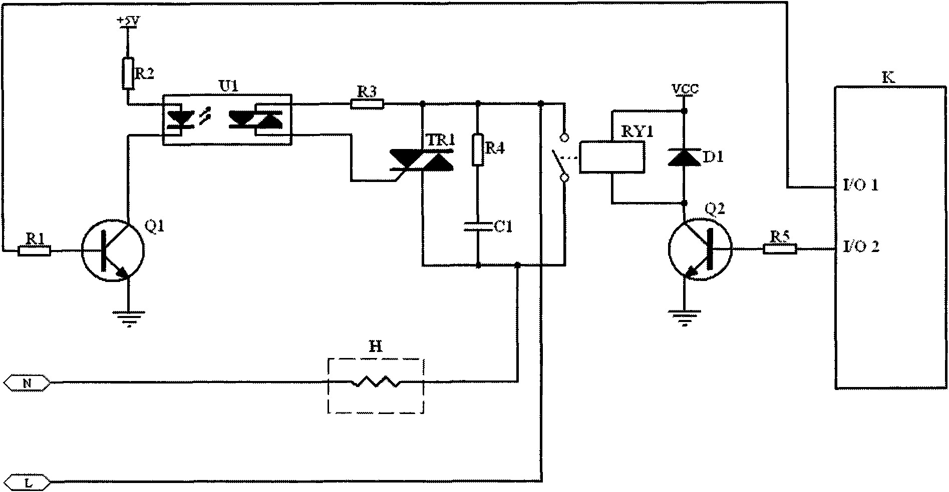
[0032] image 3 A third specific implementation manner of the protection circuit of the present invention is shown.
[0033]On the basis of Embodiment 2, the protection circuit also includes a first resistor R1, a second resistor R2, a fifth resistor R5, a diode D1, a first transistor Q1, and a second transistor Q2; the control of the optocoupler U1 The pole A is connected to the DC power supply through the second resistor R2; the emitter of the first triode Q1 is grounded, and the control pole K of the optocoupler U1 is connected to the I / O1 port of the controller K. The collector of a triode Q1, the base of the first triode Q1 is connected to one end of the first resistor R1, the other end of the first resistor R1 is connected to the I / O1 port of the controller K; the K pole of the diode D1 is connected to the VCC power supply , the A pole of the diode D1 is connected to the collector of the second triode Q2, the emitter of the second triode Q2 is grounded, and the connecti...
PUM
 Abstract
Description
Claims
Application Information
 - R&D
- Intellectual Property
- Life Sciences
- Materials
- Tech Scout
- Unparalleled Data Quality
- Higher Quality Content
- 60% Fewer Hallucinations
Browse by: Latest US Patents, China's latest patents, Technical Efficacy Thesaurus, Application Domain, Technology Topic, Popular Technical Reports.
© 2025 PatSnap. All rights reserved.Legal|Privacy policy|Modern Slavery Act Transparency Statement|Sitemap|About US| Contact US: help@patsnap.com


