
Decoder and decoding method of RFID receiver

A decoding method and decoder technology, applied in the direction of instruments, code conversion, computer components, etc., can solve the problem that the power consumption and volume requirements of portable RFID readers cannot be met, the response time cannot meet the requirements, and RFID systems are not applicable and other problems, to achieve the effect of reducing hardware resource consumption, simple structure, and solving response time

Inactive Publication Date: 2011-11-16
PEKING UNIV SHENZHEN GRADUATE SCHOOL
View PDF0 Cites 0 Cited by
  • Summary
  • Abstract
  • Description
  • Claims
  • Application Information

AI Technical Summary

Problems solved by technology

[0003] General receiver decoding methods (such as maximum likelihood estimation and interpolation filtering) are not suitable for RFID systems because the response time cannot meet the requirements.
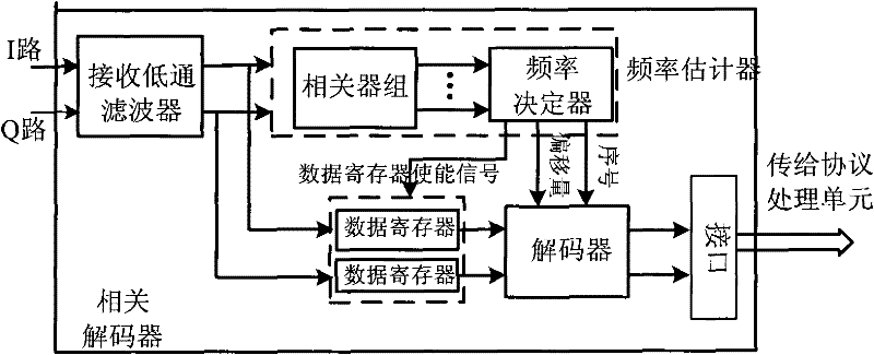
Two-step correlation demodulation method, such as figure 1 As shown, it is a decoding method that can accurately capture the return signal with a large frequency deviation, and the response speed can also meet the requirements, but because more correlators and higher sampling rates are needed in exchange for high frequency resolution , the consumption of hardware resources is very large, which cannot meet the power consumption and volume requirements of portable RFID readers

Method used


Image

  • Decoder and decoding method of RFID receiver
  • Decoder and decoding method of RFID receiver
  • Decoder and decoding method of RFID receiver

Examples


Embodiment Construction

[0036] The present invention will be described in further detail below through specific embodiments in conjunction with the accompanying drawings.

[0037] RFID receivers such as figure 2 Shown, including RF / analog front-end filtering, DC-removing blocks, decoders, and coprocessors. The RF / analog front-end filtering and DC removal module performs capacitive filtering on the signal, and then outputs it after being processed by ADC and digital filter. The output signal shape is similar to the signal shape of capacitor charging and discharging. When the data length is long, the capacitor charging and discharging If the waveform at this time is directly judged by zero-crossing detection or correlator, misjudgment may occur, because the data has been deformed by the two methods mentioned above; the decoder is located in the protocol Before the processor, the signal is decoded by FM0 encoding to restore the real signal transmitted. FM0 encoding uses level changes to represent log...


PUM


Abstract

The invention discloses a decoder of an RFID receiver, comprising an input end from which data are input, an output end from which decoded data are output and a zero-crossing detection module; wherein, the zero-crossing detection module comprises a counting unit, a coding unit and a decoding unit; the counting unit is used for counting the data input from the input end; the coding unit is used forcoding in accordance with the simplified storage format based on the output of the counting unit; the decoding unit is used for decoding the data subjected to real-time bi-phase space coding in the coding unit and outputting the decoded data from the output end. The invention also discloses a decoding method of the RFID receiver. The invention adopts the simplified storage format for coding the data, thereby dispensing with storing all the data, realizing real-time decoding and reducing consumption of hardware resources while solving the response time. The decoder is small and exquisite in structure and can be embedded into mobile phones for use.

Description

technical field [0001] The invention relates to an RFID reader-writer, in particular to a decoder and a decoding method for an RFID receiver. Background technique [0002] Today, with the rapid development of informatization, RFID (Radio Frequency Identification) technology has become a mainstream technology, and it has been widely used in logistics, libraries, medical care, etc., which has also promoted the RFID system industry. development of. The basic subsystems of the RFID system include: readers, tags and antennas. At the receiving end of the reader, after the signal reflected by the tag is demodulated by the carrier of the analog front end, it is sampled by the ADC (Analog to Digital Converter: analog-to-digital converter), and the original signal is restored by filtering, phase recovery, decoding and other modules , and then the protocol processing unit recognizes the command, so as to make corresponding operations. [0003] Common receiver decoding methods (such ...

Claims


Application Information

Patent Timeline
Patent Type & Authority Patents(China)
IPC IPC(8): G06K7/00H03M5/12
Inventor 钟金丝冯晓星齐永珍曹伟王新安
Owner PEKING UNIV SHENZHEN GRADUATE SCHOOL
Learn More