
System for compensating combined negative sequence current of power regulator and static var compensator

A technology of static reactive power compensation and power conditioner, which is applied in the direction of eliminating/reducing asymmetry in polyphase networks, reducing asymmetry in polyphase networks, etc. It can solve the problems of increasing difficulty in design and manufacture, high cost of RPC, and reduce equipment costs. cost, improved compensation effect, reduced capacity effect

Inactive Publication Date: 2009-10-28
HUNAN UNIV +1
View PDF0 Cites 24 Cited by
  • Summary
  • Abstract
  • Description
  • Claims
  • Application Information

AI Technical Summary

Problems solved by technology

When one side of the power supply arm is loaded by locomotives and the other side is empty, in order to achieve a balance of active power between the two power supply arms, the capacity of the RPC must be half of the load power of the locomotive. Taking an electric locomotive with a power of 8MVA as an example, at this time The minimum capacity of the RPC is 4MVA. The large capacity makes the cost of the RPC high, and the design and manufacture are more difficult; at the same time, due to the inherent characteristics of the V / V traction transformer, when the power of the two power supply arms is balanced and the power factor is 1, three The ratio of negative-sequence current to positive-sequence current amplitude on the phase side is still 50%, and the pure RPC structure encounters a bottleneck in negative-sequence current suppression

Method used


Image

  • System for compensating combined negative sequence current of power regulator and static var compensator
  • System for compensating combined negative sequence current of power regulator and static var compensator
  • System for compensating combined negative sequence current of power regulator and static var compensator

Examples


Embodiment Construction

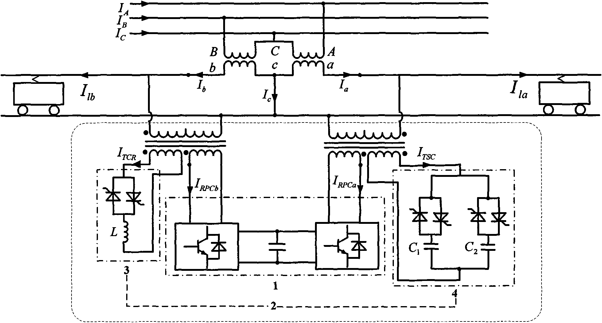
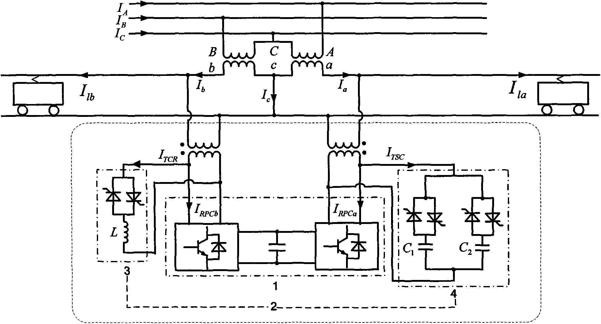
[0015] see figure 1 , figure 1 It is a structural diagram of Embodiment 1 of the present invention. The present invention includes a railway power conditioner 1 and a static var compensator 2 . Railway power conditioner 1 adopts two single-phase H-bridge inverters based on switching devices, which form a "back-to-back" structure by sharing the DC side capacitors, and the AC sides of the two inverters are connected in parallel through two single-phase three-winding step-down transformers Connect to the two-phase power supply arm on the secondary side of the traction transformer. The static var compensator 2 is composed of two sets of thyristor-controlled switching capacitors 4 (TSC) and a set of thyristor-controlled reactors 3 (TCR) connected in parallel, respectively connected in parallel to two traction power supply arms through a single-phase three-winding step-down transformer . The TSC is connected to the single-phase three-winding step-down transformer under the power...


PUM


Abstract

The invention discloses a system for compensating the combined negative sequence current of a power regulator and a static var compensator. The system consists of a railway power regulator and the static var compensator. The railway power regulator is installed between two power supplying arms at a secondary side of a traction transformer by two single-phase three-winding reducing transformer. Thestatic var compensator consists of two groups of thyristor switched capacitors which are connected in parallel and a group of thyristor controlled reactors. The thyristor switched capacitors and thethyristor controlled reactors are respectively connected with two traction power supplying arms by single-phase three-winding reducing transformers, wherein the thyristor switched capacitors are installed below the single-phase three-winding reducing transformer which is connected with the power supplying arms with relatively advanced voltage phases, and the thyristor controlled reactors are installed below the single-phase three-winding reducing transformer of the power supplying arms with relatively hysteretic voltage phases. The system can maximally reduce the capacity of the railway powerregulator while also satisfying the requirement of a railway system on the unbalancedness degree of three phase current.

Description

technical field [0001] The invention relates to a negative-sequence current compensation system for an electrified high-speed railway, in particular to a combined negative-sequence current compensation system for a power regulator and a static var compensator suitable for an electrified high-speed railway. Background technique [0002] Most of the electrified railway traction substations in my country use special traction transformers to transmit the electric energy of the three-phase power system to two single-phase traction lines with their respective loads. Due to the adjustment function of the locomotive itself, the traction load of the two power supply arms of the traction substation is Independent of each other and randomly fluctuating, because of the asymmetry of the traction load, the three-phase currents on the high and low voltage sides of the traction transformer are unbalanced, and negative sequence currents are generated on the system side bus. Negative-sequence ...

Claims


Application Information

Patent Timeline
Patent Type & Authority Applications(China)
IPC IPC(8): H02J3/26
CPCY02E40/50
Inventor 罗安王文吴传平马伏军徐先勇杨晓赵伟王刚
Owner HUNAN UNIV
Learn More