Combination for capacitor electrode adhesive
A capacitor electrode and composition technology, which is applied in the direction of hybrid capacitor electrodes, capacitors, hybrid capacitor collectors, etc., can solve problems such as blocking and capacitor electrodes hindering lithium doping, and achieve good electrode activity.
- Summary
- Abstract
- Description
- Claims
- Application Information
AI Technical Summary
Problems solved by technology
Method used
Image
Examples
Embodiment 1
[0108] (Polymerization process of fluoropolymer)
[0109] After fully replacing nitrogen in an autoclave with an internal volume of about 6L equipped with an electromagnetic stirrer, add 2.5L of deoxygenated purified water and 25g of ammonium perfluorodecanoate as an emulsifier, and heat up to 60°C while stirring at 350rpm. ℃. Next, add a mixed gas composed of 70% vinylidene fluoride (VDF) and 30% hexafluoropropylene (HFP) until the internal pressure reaches 20kg / cm 2 g. Then, 25 g of a fluorocarbon 113 solution containing 20% of diisopropyl peroxydicarbonate was injected as a polymerization initiator using nitrogen gas to start polymerization. In order to keep the internal pressure during polymerization at 20kg / cm 2 G, press in sequence the mixed gas composed of 60.2% VDF and 39.8% HFP. And, as the polymerization progresses, since the polymerization rate decreases, after 3 hours, the same amount of polymerization initiator as before was injected using nitrogen pressure,...
Embodiment 2
[0115] (Polymerization process of fluoropolymer)
[0116] After fully replacing nitrogen in an autoclave with an internal volume of about 6L equipped with an electromagnetic stirrer, add 2.5L of deoxygenated purified water and 50g of ammonium perfluorodecanoate as an emulsifier, and heat up to 60°C while stirring at 350rpm. ℃. Next, add a mixed gas composed of 70% vinylidene fluoride (VDF) and 30% hexafluoropropylene (HFP) until the internal pressure reaches 20kg / cm 2 g. Then, 25 g of a fluorocarbon 113 solution containing 20% of diisopropyl peroxydicarbonate was injected as a polymerization initiator using nitrogen gas to start polymerization. In order to keep the internal pressure during polymerization at 20kg / cm 2 G, press in sequence the mixed gas composed of 60.2% VDF and 39.8% HFP. And, according to the progress of the polymerization, since the polymerization rate decreased, after 3 hours, the same amount of the polymerization initiator as before was injected using...
Embodiment 3~5
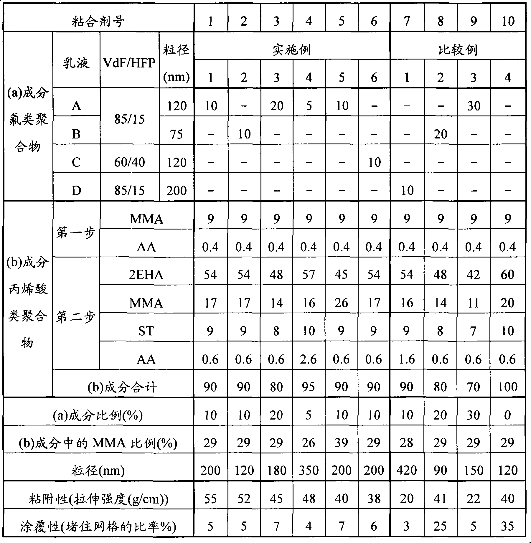
[0120] Except having used the polymerizable monomer as shown in following Table 1, it carried out similarly to Example 1, and obtained the aqueous dispersion medium [3]-[5].
[0121] Table 1 shows the number average particle diameters of the polymer particles [3] to [5] in the obtained aqueous dispersion media [3] to [5].
PUM
| Property | Measurement | Unit |
|---|---|---|
| Number average particle size | aaaaa | aaaaa |
| Number average particle size | aaaaa | aaaaa |
| Number average particle size | aaaaa | aaaaa |
Abstract
Description
Claims
Application Information
 - R&D
- Intellectual Property
- Life Sciences
- Materials
- Tech Scout
- Unparalleled Data Quality
- Higher Quality Content
- 60% Fewer Hallucinations
Browse by: Latest US Patents, China's latest patents, Technical Efficacy Thesaurus, Application Domain, Technology Topic, Popular Technical Reports.
© 2025 PatSnap. All rights reserved.Legal|Privacy policy|Modern Slavery Act Transparency Statement|Sitemap|About US| Contact US: help@patsnap.com

