
Device and method for recycling volatile substances by utilizing adsorbent bed

A technology for volatile substances and adsorption beds, applied in separation methods, chemical instruments and methods, filter regeneration, etc., can solve the problems of failure to further improve efficiency, reduce the adsorption function of the adsorption bed 1, and waste the environment of volatile substances, etc. problems, achieve the effect of reducing waste, improving adsorption effect and saving energy

Inactive Publication Date: 2011-08-10
刘伍雄
View PDF0 Cites 0 Cited by
  • Summary
  • Abstract
  • Description
  • Claims
  • Application Information

AI Technical Summary

Problems solved by technology

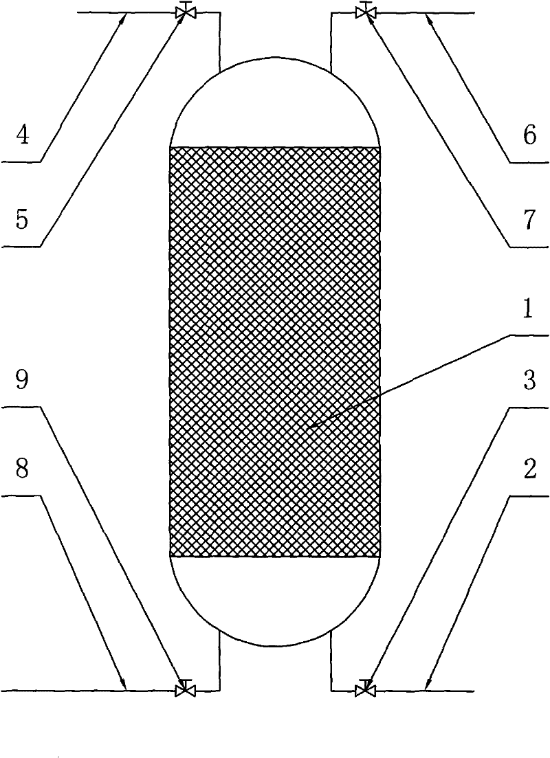
Such technological process has the following problems: 1) in the desorption process, continuously feed large-flow steam, make adsorption bed 1 lower part temperature reach more than 100 ℃, and the boiling point of volatile matter is generally no more than 100 ℃ (as dichloromethane The boiling point is only 39.8°C), which causes waste of steam energy; 2) at the end of the desorption, simultaneously close the steam valve 7 and the desorption valve 9 and simultaneously open the inlet valve 3 and the exhaust valve 5, so that in the final stage of desorption The steam introduced in 2 to 3 minutes is vainly discharged into the atmosphere, which further causes a waste of steam energy, and at the beginning of the adsorption step, due to the high temperature and high humidity of the adsorption bed, it greatly reduces the Due to the adsorption function of the adsorption bed 1, the concentration of volatile substances in the tail gas is relatively high, resulting in waste of volatile substances and environmental pollution. The patent application with application number 200710028613 provides a method for recovering volatile substances with an adsorption bed. This method solves the above problems, but its efficiency cannot be further improved because the auxiliary power air intake device is not used in this method

Method used


Image

  • Device and method for recycling volatile substances by utilizing adsorbent bed
  • Device and method for recycling volatile substances by utilizing adsorbent bed
  • Device and method for recycling volatile substances by utilizing adsorbent bed

Examples


Embodiment 1

[0044] The method that the present invention reclaims methylene chloride with adsorption bed comprises the following two steps:

[0045] (1) adsorption step, open intake valve 3, tail gas valve 5; close steam valve 7, desorption valve 9;

[0046] (2) desorption step, open steam valve 7, desorption valve 9; close intake valve 3, tail gas valve 5.

[0047] The technological process of described desorption step is carried out according to the following method:

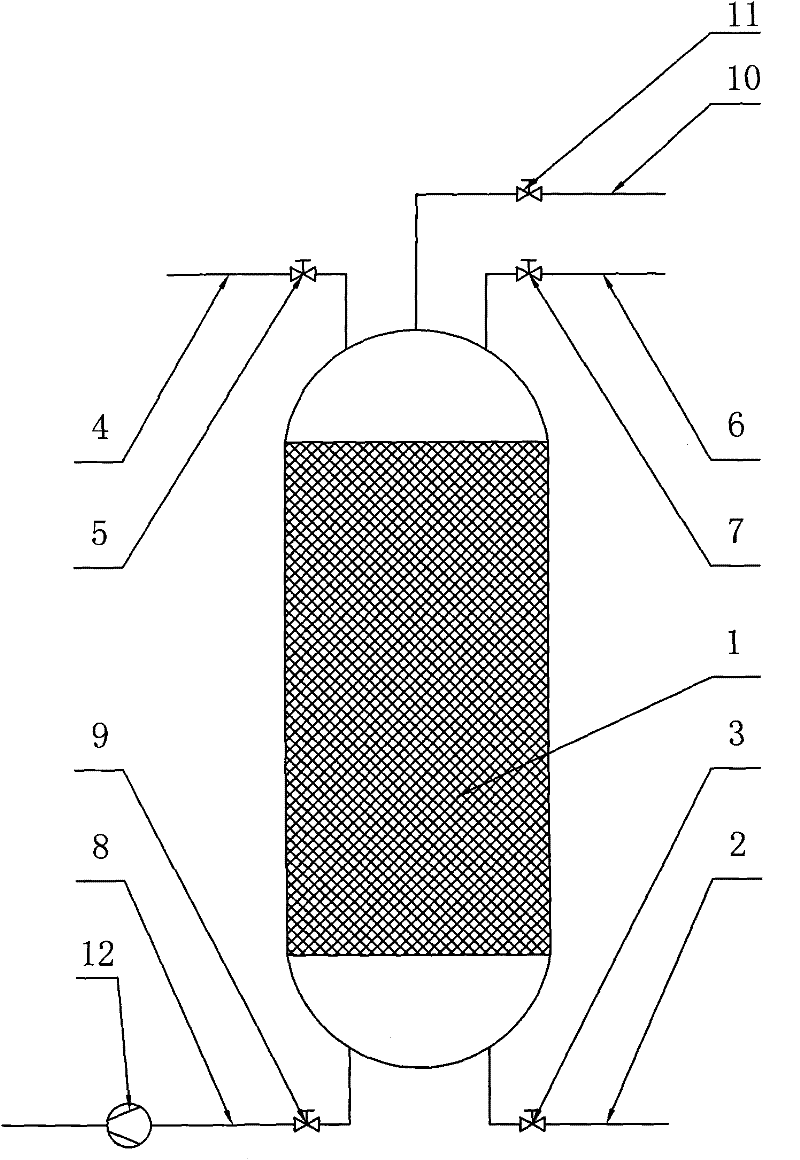
[0048] Open the steam valve 7, open the desorption valve 9, heat the adsorption bed 1 with steam, and delay for more than 1 minute. When the temperature of the mixed gas injection end of the adsorption bed 1 reaches or exceeds 39.8°C, close the steam Valve 7, open the power intake valve 11, delay more than 20 seconds, close the power intake valve 11, then close the desorption valve 9, then open the tail gas valve 5, open the intake valve 3 to enter The adsorption step.

Embodiment 2

[0050] The method that the present invention reclaims methylene chloride with adsorption bed comprises the following two steps:

[0051] (1) adsorption step, open intake valve 3, tail gas valve 5; close steam valve 7, desorption valve 9;

[0052] (2) desorption step, open steam valve 7, desorption valve 9; close intake valve 3, tail gas valve 5.

[0053] The technological process of described desorption step is carried out according to the following method:

[0054] Open the steam valve 7, open the desorption valve 9, heat the adsorption bed 1 with steam, delay for more than 1 minute, and close the steam valve 7 when the temperature of the mixed gas injection end of the adsorption bed 1 reaches or exceeds 39.8°C , open the power intake valve 11, delay more than 20 seconds, close the power intake valve 11, start the gas aspirator 12, delay more than 20 seconds, stop the gas aspirator 12, and then close The desorption valve 9 is then opened to the tail gas valve 5, and the int...

Embodiment 3

[0056] The method that the present invention reclaims methylene chloride with adsorption bed comprises the following two steps:

[0057] (1) adsorption step, open intake valve 3, tail gas valve 5; close steam valve 7, desorption valve 9;

[0058] (2) desorption step, open steam valve 7, desorption valve 9; close intake valve 3, tail gas valve 5.

[0059] The technological process of described desorption step is carried out according to the following method:

[0060] Open the steam valve 7, open the desorption valve 9, heat the adsorption bed 1 with steam, delay for more than 1 minute, when the temperature of the mixed gas injection end of the adsorption bed 1 reaches or exceeds 39.8°C, open the power intake Valve 11, delay more than 20 seconds, close the steam valve 7, delay more than 20 seconds, close the power intake valve 11, then close the desorption valve 9, then open the exhaust valve 5, open the intake Valve 3 enters the adsorption step.


PUM

PropertyMeasurementUnit
boiling pointaaaaaaaaaa

Abstract

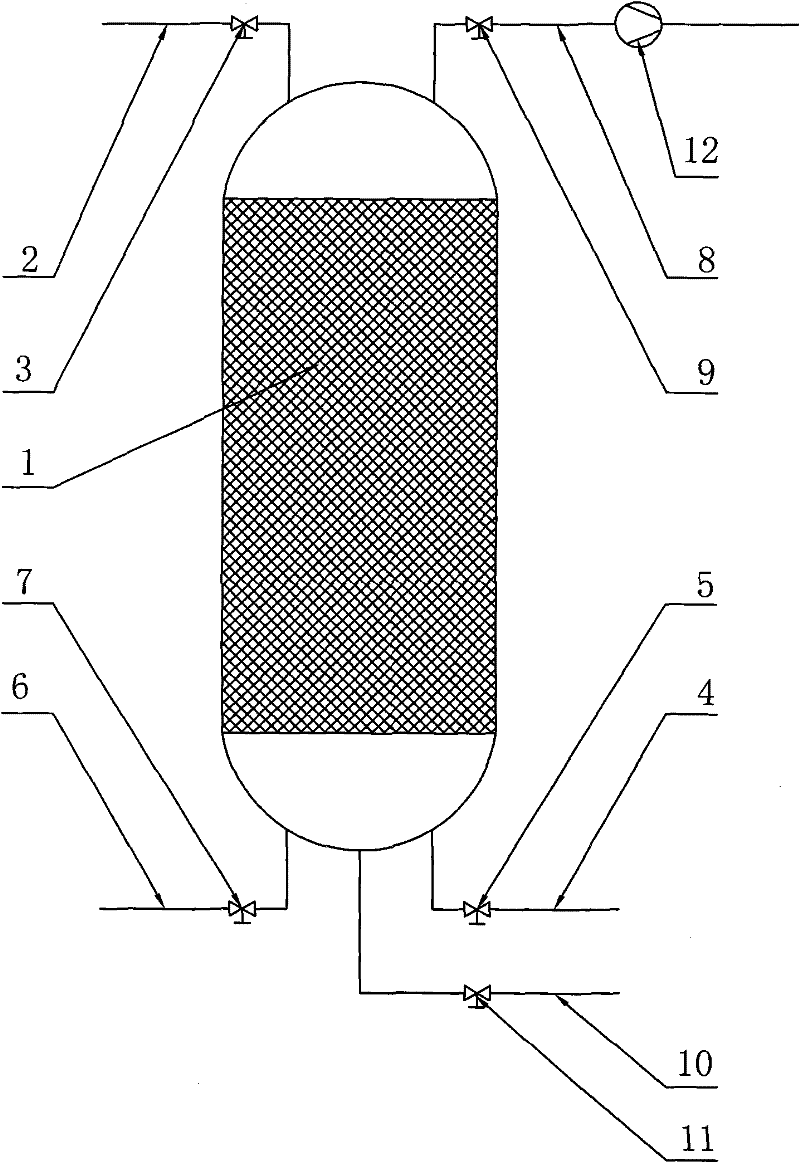
The invention discloses a device and a method for recycling volatile substances by utilizing an adsorbent bed, which have the advantages of high efficiency and energy saving. The device comprises an adsorbent bed (1), wherein a mixing gas injection end of the adsorbent bed (1) is connected with a mixing gas pipeline (2) and a desorption pipeline (8). A gas inlet valve (3) is arranged on the mixing gas pipeline (2), and a desorption valve (9) is arranged on the desorption pipeline (8). A steam supply end of the adsorbent bed (1) is connected with a tail gas pipeline (4) and a steam pipeline (6), wherein a tail gas valve (5) is arranged on the tail gas pipeline(4), and a steam valve (7) is arranged on the steam pipeline (6). The steam supply end of the absorbent bed (1) is also connected with a power gas inlet pipe (10), and a power gas inlet valve (11) is arranged on the power gas inlet pipe (10). The invention can be widely applied to chemical engineering field, especially the fields for recycling volatile substances.

Description

technical field [0001] The invention relates to a device and method for recovering volatile substances with an adsorption bed. Background technique [0002] Adsorption beds are widely used in modern industry for the removal and recovery of volatile substances from process gas streams such as air or nitrogen streams. Such as figure 1 As shown, the structure of the currently used adsorption bed is mainly as follows: the adsorbent is used as the adsorption bed 1 in a closed room, and the lower part of the adsorption bed 1 is connected with the mixed gas (air containing volatile substances) inlet pipe 2 to carry out Gas pipeline 2 is provided with inlet valve 3, the upper part of adsorption bed 1 is connected with tail gas pipeline 4, and tail gas pipeline 4 is provided with tail gas valve 5, and the upper part of adsorption bed 1 is also connected with steam pipeline 6, and said steam pipeline 6 is provided with a steam valve 7, and the lower part of the adsorption bed 1 is a...

Claims


Application Information

Patent Timeline
Patent Type & Authority Patents(China)
IPC IPC(8): B01D53/04B01J20/34
Inventor 刘伍雄
Owner 刘伍雄
Learn More