


Quick Research
Generate reliable direction feasibility study reports for your R&D in just a few steps.

Technical Q&A
Discover and master advanced knowledge NOW. Basics, ideas, possibilities, all at once.

Find Solutions
As an expert in R&D theories, this can generate solutions to your technical problems instantly.

Evaluate Feasibility
Analyze your overall solution with one click, know your potential R&D risks in advance.

Monitor Landscape
Get weekly tech updates, stay abreast of the latest tech innovations and key insights.
Battery pack, battery-mounted device and connection structure for battery pack
A technology for battery assembly and battery loading, which is applied to battery pack components, small-sized batteries/battery packs, batteries, etc., and can solve problems such as damage to battery packs, damage expansion, etc.
- Summary
- Abstract
- Description
- Claims
- Application Information
AI Technical Summary
Problems solved by technology
Method used
Image


Examples
Embodiment approach 2
[0064] The battery pack 12 in the second embodiment is different from the battery packs in the above-mentioned embodiments in that it includes a connecting pipe portion 12H, a gas cooling portion 12L, and a connecting portion 12P as exhaust ducts. In other words, the spark trap 12M and the exhaust port 12Y are installed on the battery-mounted device side, that is, on the main body side of the electric bicycle 14 as an external path. -
[0065] That is, by mounting the battery pack 12 in the electric bicycle 14, the exhaust duct (connection portion 12P) on the battery pack 12 side and the external path (gas cooling portion 12L) on the electric bicycle 14 side are joined at the junction point P2 . Gas generated during abnormality is released to the bottom side (below) of the electric bicycle 14 opposite to the side (upper) on the passenger side of the electric bicycle 14 via the gas cooling portion 12L on the battery pack 12 side and the joint portion P2.
[0066] Next, Embodi...
Embodiment 1A
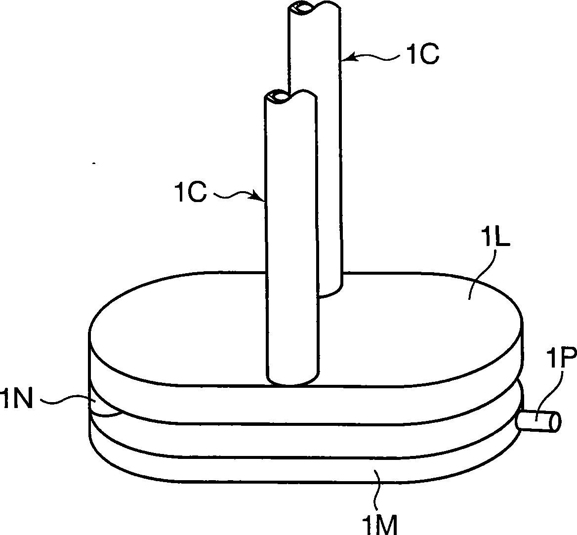
[0083] Will figure 1 The illustrated battery pack 1D and exhaust duct 1C are housed inside the battery packs 1A, 1B, and the outer peripheries of the battery packs 1A, 1B are welded. At this time, for the completed battery pack, set the maximum charging current to 3A and the charging termination current to 0.1A, which can usually be charged to 12.6V, but the overcharge protection circuit of the bypass battery pack and the current of the battery Blocking (CID), it can be charged to 13.5V with constant current and constant voltage. Such a battery pack was referred to as the battery pack of Example 1A.
Embodiment 1B
[0085] A porous ceramic plate with a thickness of 1 mm (honeycomb ceramics for industrial use, ceramichoneycomb; manufactured by Nippon Baruko Co., Ltd.) was pasted inside the spark trap 1M. The arrangement position of the porous ceramic plate is the opposite wall to the wall connected to the communication pipe 1N. Except for this, a battery pack was produced in the same manner as in Example 1A, and it was used as a battery pack in Example 1B.
PUM
| Property | Measurement | Unit |
|---|---|---|
| height | aaaaa | aaaaa |
| particle diameter | aaaaa | aaaaa |
| particle diameter | aaaaa | aaaaa |
Abstract
Description
Claims
Application Information
 - R&D Engineer
- R&D Manager
- IP Professional
- Industry Leading Data Capabilities
- Powerful AI technology
- Patent DNA Extraction
Browse by: Latest US Patents, China's latest patents, Technical Efficacy Thesaurus, Application Domain, Technology Topic, Popular Technical Reports.
© 2024 PatSnap. All rights reserved.Legal|Privacy policy|Modern Slavery Act Transparency Statement|Sitemap|About US| Contact US: help@patsnap.com