
Amino multisection counterflow exhaust smoke processing device and method

A processing device and countercurrent technology, which is applied in the field of flue gas desulfurization devices, flue gas treatment or flue gas purification devices, can solve problems such as complex structure, easy waste of raw material ammonia, and difficult operation of desulfurization devices

Inactive Publication Date: 2009-08-26
王建敏
View PDF4 Cites 9 Cited by
  • Summary
  • Abstract
  • Description
  • Claims
  • Application Information

AI Technical Summary

Problems solved by technology

However, the structure is still slightly complicated due to a special layer of packing section for cleaning flue gas and removing water vapor and acid mist, and since water vapor is a kind of gas, acid mist is also an aerosol, both of which are very It is difficult to remove through simple components or methods, the efficiency is low, and there is no practical application value; the gas-liquid ratio is still too high, 200-2500, and in the actual use process, due to the use of an empty tower structure without packing, there will be Because the liquid flow rate is too small and the mass transfer specific surface area is too small, it still has the disadvantages of unstable desulfurization efficiency and easy waste of raw material ammonia. Moreover, there are only two absorption liquid circulation systems, and each spray system is equipped with multiple sprays Layers, resulting in too complex structure in the tower, and in practical applications, it is easy to cause the desulfurization device to be difficult to operate due to failure or even damage of the circulating pump

Method used


Image

  • Amino multisection counterflow exhaust smoke processing device and method
  • Amino multisection counterflow exhaust smoke processing device and method

Examples


Embodiment Construction

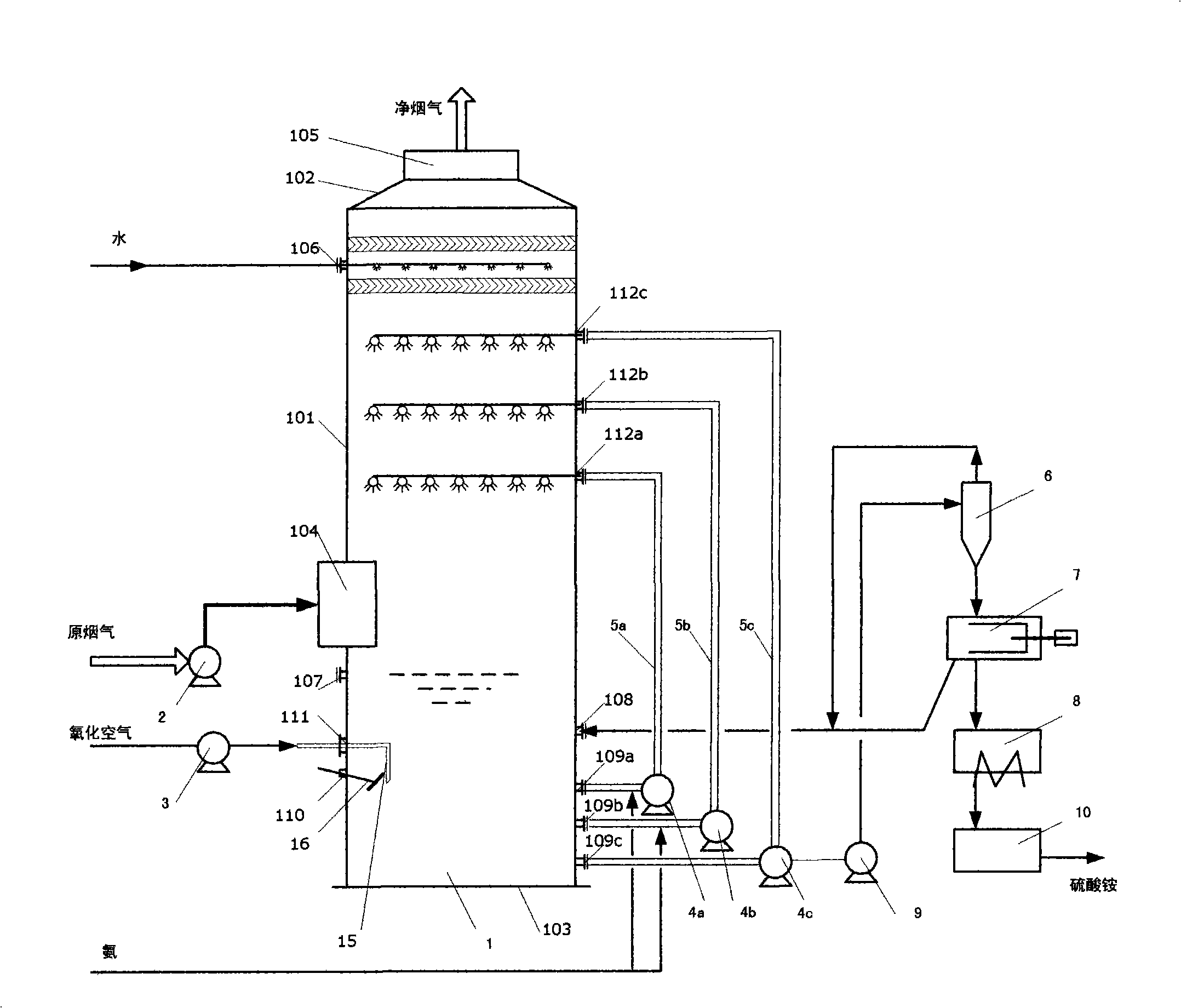
[0045] The technology of the present invention will be described in more detail below with reference to the accompanying drawings for the flue gas of a coal-fired power generation boiler.

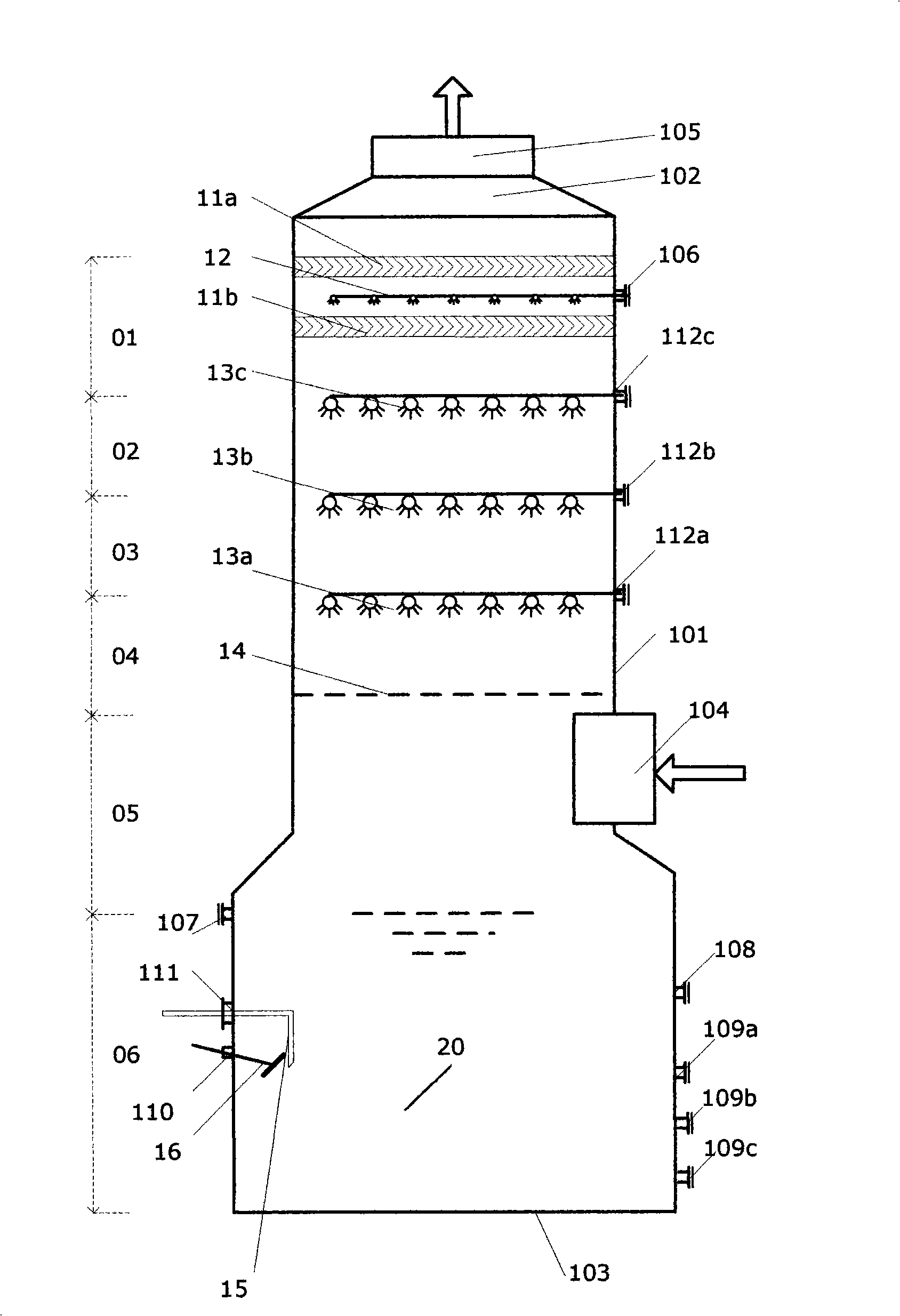
[0046] see figure 1 and figure 2 , an amino multi-stage countercurrent smoke exhaust treatment device of the present invention includes a desulfurization tower 1, and a flue gas outlet connecting pipe 105 is arranged on its top 102 or upper tower body 101; below the flue gas outlet connecting pipe 105, there are successively from top to bottom Gas-liquid separator 11, upper absorber 13c, middle absorber 13b, lower absorber 13a, flue gas homogenizer 14 and oxidizer 20, and flue gas is arranged between flue gas homogenizer 14 and oxidizer 20 Import takes over 104. Designed in this way, from the tower top 102 to the tower bottom 103, it is divided into gas-liquid separation section 01, deamination section 02, deamination and desulfurization section 03, desulfurization section 04, flue gas u...


PUM


Abstract

The invention discloses an amino multisection counterflow exhaust smoke processing device and a method thereof. The invention takes volatile ammonia as raw material and the recovered acid waste gas as useful product. The innovation of the invention essentially lines in providing three independent absorption liquid circulating systems and a standby circulating system, so that the device has six functions comprising uniform gas distribution and gas-liquid separation; the device is provided with six gas-liquid contacting components comprising a uniform distribution device and a foam destroyer; more particularly, the size of an absorption liquid circulating pipe and the absorption liquid circulating quantity are optimized, so that the ratio between the diameters of a circulating pipeline and equipment is 0.04-0.1; meanwhile, the running gas-liquid ratio is set to be 70-195. Compared with the prior art, the stability and reliability of the device are greatly improved, ammonia escape loss can be effectively controlled, the energy consumption is low, and the structure of the device is simple, thus preventing the device from scarring and being blocked as well as saving investment and running cost. Therefore, the invention has obvious advantages in the smoke removing and purifying fields such as a boiler, etc.

Description

technical field [0001] The invention relates to a device and method for flue gas treatment, that is, flue gas purification, in particular to a flue gas desulfurization device and method for recovering sulfur oxides from flue gas to produce useful products based on ammonia as a raw material, belonging to electric power, metallurgy, Environmental protection and chemical engineering and other technical fields. Background technique [0002] Thermal power plants that use coal or oil as fuel, and sintering machines in iron and steel plants emit a large amount of flue gas, that is, flue gas, which contains SO 2 , SO 3 , NO 2 , NO, HCl and HF and other acidic gaseous harmful substances, especially SO 2 It is the main substance that forms acid rain. One way to solve acid rain pollution is to purify flue gas, especially flue gas desulfurization (FGD, Flue Gas Desulfurization) using alkaline substances as raw materials. [0003] According to the different raw materials used, the c...

Claims


Application Information

Patent Timeline
Patent Type & Authority Applications(China)
IPC IPC(8): B01D53/78B01D53/50
Inventor 王建敏
Owner 王建敏
Learn More