
Method for electroplating tin-copper

A technology of electroplating tin on copper metal, applied in the field of electroplating composite metal layers on the outer lead pins of integrated circuits, which can solve the problems of fast electroplating speed and low manufacturing cost, and achieve the effect of fast electroplating speed, high production efficiency and uniform distribution of copper components

Inactive Publication Date: 2009-08-19
WUXI WELNEW MICRO ELECTRONICS
View PDF0 Cites 4 Cited by
  • Summary
  • Abstract
  • Description
  • Claims
  • Application Information

AI Technical Summary

Problems solved by technology

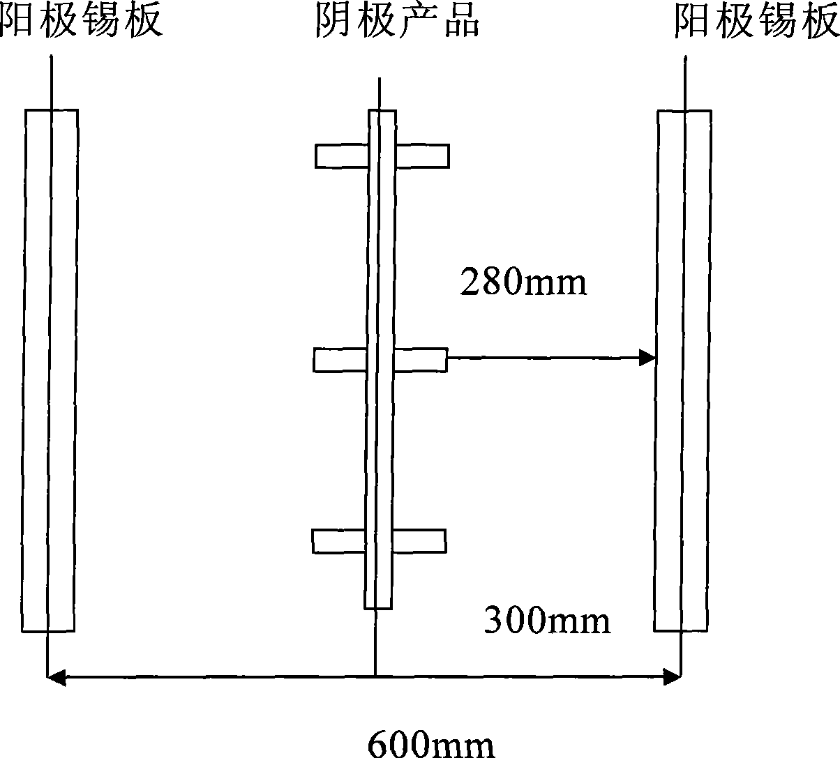
[0004] The present invention studies and improves the above-mentioned inhomogeneity problem of the tin-copper electroplating layer in the prior art, and provides a method for electroplating a tin-copper metal layer. The tin-copper metal layer electroplated by the method can meet the uniformity requirement, and the process is simple , Low manufacturing cost, fast plating speed

Method used


Image

  • Method for electroplating tin-copper
  • Method for electroplating tin-copper
  • Method for electroplating tin-copper

Examples


Embodiment 1

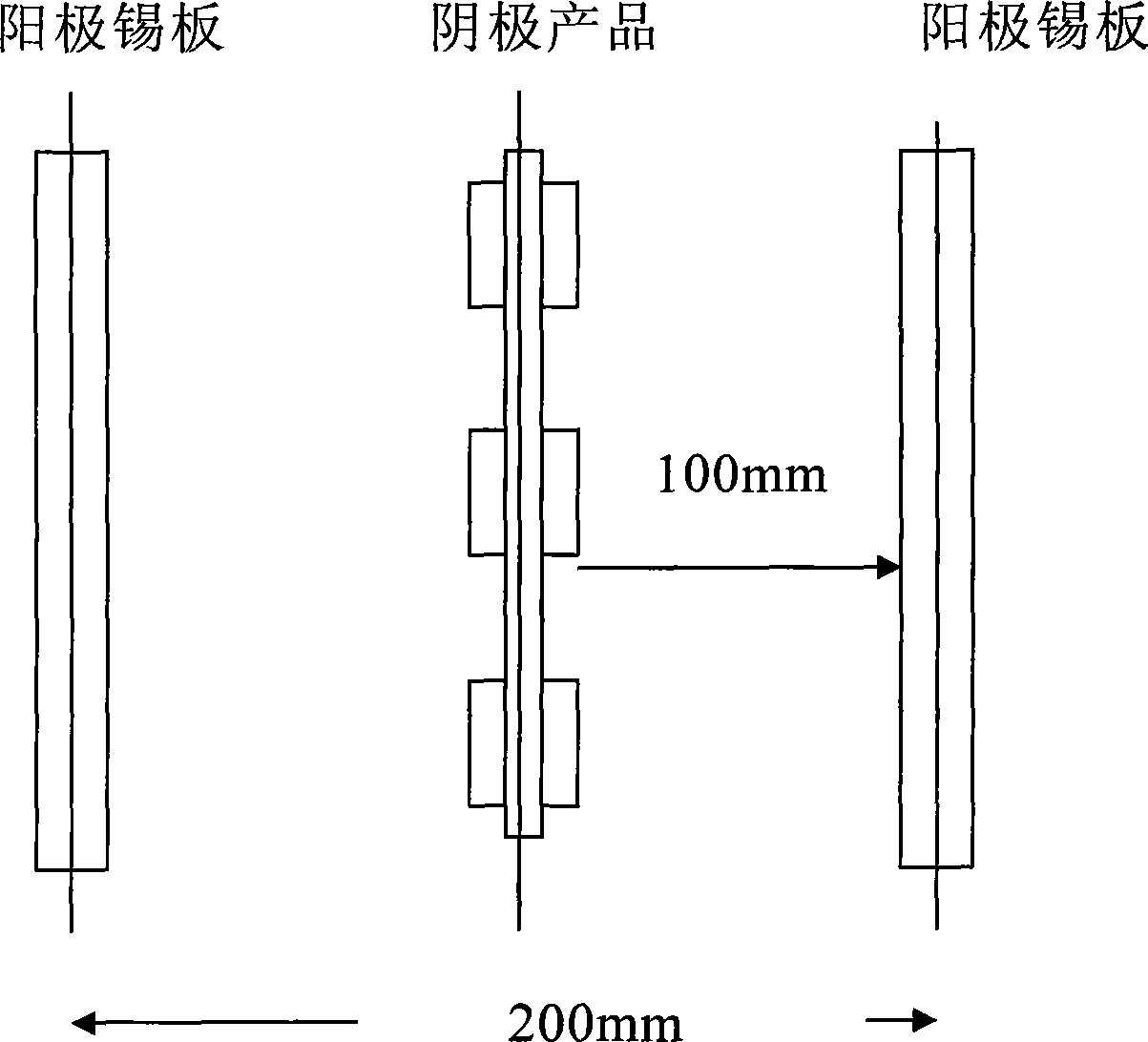
[0037] Get 50 products to be electroplated (the outer leads of the TSOP48 integrated circuit package shell), such as figure 2 Attach and fix on the cathode transmission steel belt with spring clips, the distance between the steel belt and the two anode plates is equal, both are 100mm, see figure 2 . The material of the anode plate is a tin plate, and the dimensions are: length 500 mm, width 30 mm, height 100 mm.

[0038] Cathode conveying steel belt speed: 4.5m / min.

[0039] The formula of electroplating solution, electroplating process steps and process conditions are as follows.

[0040]

[0041]

[0042] The additive SNC21 in the electroplating solution formula in the above table can prevent the reduction of coverage in low current density areas; the SNC22 additive can avoid the oxidation of divalent tin and prevent the replacement reaction of copper and anode tin; the SNC23 additive can make the coating bright and crystallized.

[0043] Take 10 lead electroplati...

Embodiment 2

[0049] Cathode conveying steel belt speed: 5m / min.

[0050] The formula, electroplating process steps and process conditions of the electroplating solution are as follows, and other process descriptions are the same as in Example 1.

[0051]

[0052]

[0053] Its measurement data are as follows:

[0054]

[0055]

Embodiment 3

[0057] Cathode conveying steel belt speed: 5.5m / min.

[0058] The formula, electroplating process steps and process conditions of the electroplating solution are as follows, and other process descriptions are the same as in Example 1.

[0059]

[0060] Its measurement data are as follows:

[0061]

[0062]

[0063] It can be seen from the data of the above examples that the plating layer of the product electroplated by the method of the present invention has a uniform thickness and a uniform copper content.


PUM


Abstract

A method for electroplating a tin copper metal layer is characterized in that the formulation of the electroplating liquid is: in terms of mass volume ratio, 30-80g / l of tin methyl sulphonate and 0.5-3g / l of copper methyl sulphonate; in terms of volume ratio, 50-250ml / l of methyl sulfoacid, 30-80ml / l of additive SNC21 (produced by Germany Schlotter), 50-200ml / l of additive SNC22 (produced by Germany Schlotter), 5-15ml / l of additive SNC23 (produced by Germany Schlotter), and the balance of water; the current density of the electroplating solution is 10-20 ampere / square decimeter, the temperature is 35-65 DEG C, and the electroplating period is 1.5-2.5min. The cathode board in the electroplating tank which contains the electroplating solution servers as a conveying steel band, and the electroplated item has equal or similar distance with the two anode boards. The tin copper metal layer prepared by the method has uniform thickness, evenly distributed copper component, and excellent weldability.

Description

Technical field: [0001] The technology relates to a method for electroplating a compound metal layer, in particular to a method for electroplating a compound metal layer for an integrated circuit outer lead pin. Background technique: [0002] Tin-copper electroplating technology is widely used in PCB (printed circuit board) and IC integrated circuit electroplating. Compared with tin-lead electroplating, tin-copper electroplating is non-toxic, low in corrosion, bright in coating, good in solderability, and simple in wastewater treatment, etc. It is a green and environmentally friendly electroplating system that countries around the world are currently committed to promoting and using. The copper component of tin-copper electroplating is 1-3%, wherein the uniformity of plating thickness is an important index affecting product quality, and the tin-copper electroplating of the present invention solves the problem of uneven thickness. [0003] At present, the production of tin-c...

Claims


Application Information

Patent Timeline
IPC IPC(8): C25D3/60C25D7/06
Inventor 薛永健涂利彬
Owner WUXI WELNEW MICRO ELECTRONICS
Learn More