Concrete continuous stirring and conveying system device

A conveying system and concrete technology, which is applied in the direction of cement mixing device, clay preparation device, mixing operation control device, etc. It can solve the problems of large installation space, low productivity, and occupation of weighing scales, etc.

Inactive Publication Date: 2009-08-05
邓嘉鸣 +2
View PDF0 Cites 15 Cited by
  • Summary
  • Abstract
  • Description
  • Claims
  • Application Information

AI Technical Summary

Problems solved by technology

[0003] Concrete mixers include drum mixers, conical inverted discharge mixers, conical tilting discharge mixers, vertical vortex mixers, and horizontal shaft forced mixers. These mechanical structures are not complicated, easy to maintain, and have no technical requirements for operation. High, good work reliability, but this kind of mixer has low degree of mechanization, poor weighing equipment, low productivity, difficult to guarantee the quality of concrete, discontinuous discharge, low production efficiency
[0004] The concrete mixing plant (building) can apply advanced electronic technology to the batching and quality control system, and can supply various concrete mixtures to the construction site in time. It has the advantages of high mechanization, automation, high yield, high quality, and low cost, but Large-scale mixing buildings must have a number of matching mixer trucks, and various weighing scales will take up a large installation space, and there must be enough pumping equipment on the construction site, which requires a large amount of investment at one time, especially the lack of project concentration, concrete Projects with a large amount of pouring will appear uneconomical when there is "no food to eat"

Method used


Image

  • Concrete continuous stirring and conveying system device

Examples


Embodiment Construction

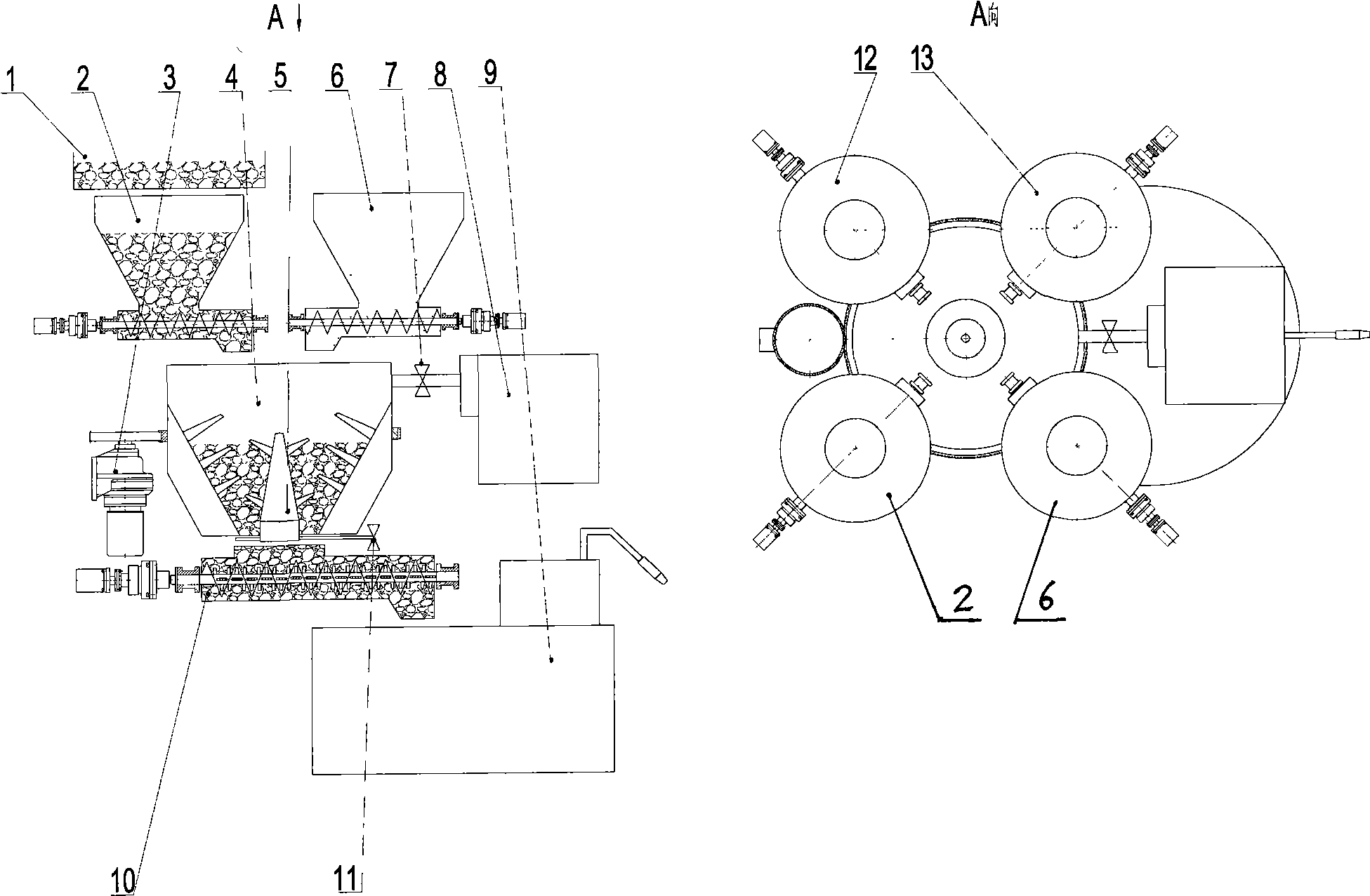
[0012] The following will be combined with figure 1 Embodiments of the present invention will be described in detail.

[0013] A continuous concrete mixing and conveying system device, which consists of a gravel sieve 1, a gravel metering and conveying system 2, a concrete mixing drum drive motor 3, a concrete mixing drum 4, a fixed concrete mixer 5, a sand metering and conveying system 6, and a water inlet regulating valve 7. Water tank and pumping system 8. Concrete storage tank and pumping system 9. Concrete secondary mixing and conveying system 10. Concrete conveying regulating valve 11. Cement metering and conveying system 12. Additive metering and conveying system 13. The whole system works At this time, by controlling the motor speed of the metering and conveying system of each component, the feeding amount of each component during the mixing of the whole system can always maintain the required concrete ratio. in:

[0014] The gravel metering conveying system 2, the s...


PUM


Abstract

The invention relates to a concrete continuous mixing and conveying system device, which comprises a stone screen (1), a stone measuring and conveying system (2), a concrete mixing cylinder driving motor (3), a concrete mixing cylinder (4), a concrete fixed mixer (5), a sand measuring and conveying system (6), a water feed regulating valve (7), a water tank and a pumping system (8), a concrete storage tank and a pumping system (9), a concrete secondary mixing and conveying system (10), a concrete discharge regulating valve (11), a cement measuring and conveying system (12), an additive measuring and conveying system (13), and the like; the feed mode of concrete solid components adopts a screw rod continuous pumping mode, and the concrete is fully and intensely mixed at one time after the concrete enters the concrete mixing cylinder (4) of which the inner wall is provided with compulsory mixing blades; and the mixed concrete is put into the concrete secondary mixing and conveying system (10) through the concrete discharge regulating valve (11) for the second mixing and then pumped into the concrete storage tank (9). The whole system can maintain the required concrete mixture ratio through control, can continuously mix and discharge the concrete, and has high production efficiency.

Description

technical field [0001] The invention relates to construction engineering fields such as high-grade roads, wharfs, bridges, building constructions, and airport runways, and specifically provides an ingenious and efficient concrete continuous mixing and conveying system device for the field of concrete use. Background technique [0002] With the rapid development of society and economy, concrete is widely used in the construction of high-grade roads, docks, bridges, housing construction, airport runways, etc. in various places. Concrete is generally composed of solid components (stones, sand, cement, additives, etc.) and water, etc. It is mixed according to a certain proportion and fully stirred. The freshly mixed concrete is in a flow-plastic state within a certain period of time and can be cast into structures and components of any shape. After a period of time after forming, the cement and water undergo hydration reactions. , so that the concrete hardens and has high compre...

Claims


Application Information

Patent Timeline
Patent Type & Authority Applications(China)
IPC IPC(8): B28C9/02B28C7/04B28C5/08
Inventor 邓嘉鸣沈惠平徐晓霖
Owner 邓嘉鸣
Why Eureka
Try Eureka