Position matching method and screen printer

A technology of screen printing and printing table, applied in the direction of screen printing, screen printing machine, printing, etc.

Active Publication Date: 2009-07-22
YAMAHA MOTOR CO LTD
View PDF0 Cites 29 Cited by
  • Summary
  • Abstract
  • Description
  • Claims
  • Application Information

AI Technical Summary

Problems solved by technology

Therefore, there is room for improvement on this

Method used


Image

  • Position matching method and screen printer
  • Position matching method and screen printer
  • Position matching method and screen printer

Examples


Embodiment Construction

[0024] Hereinafter, embodiments of the present invention will be described with reference to the accompanying drawings.

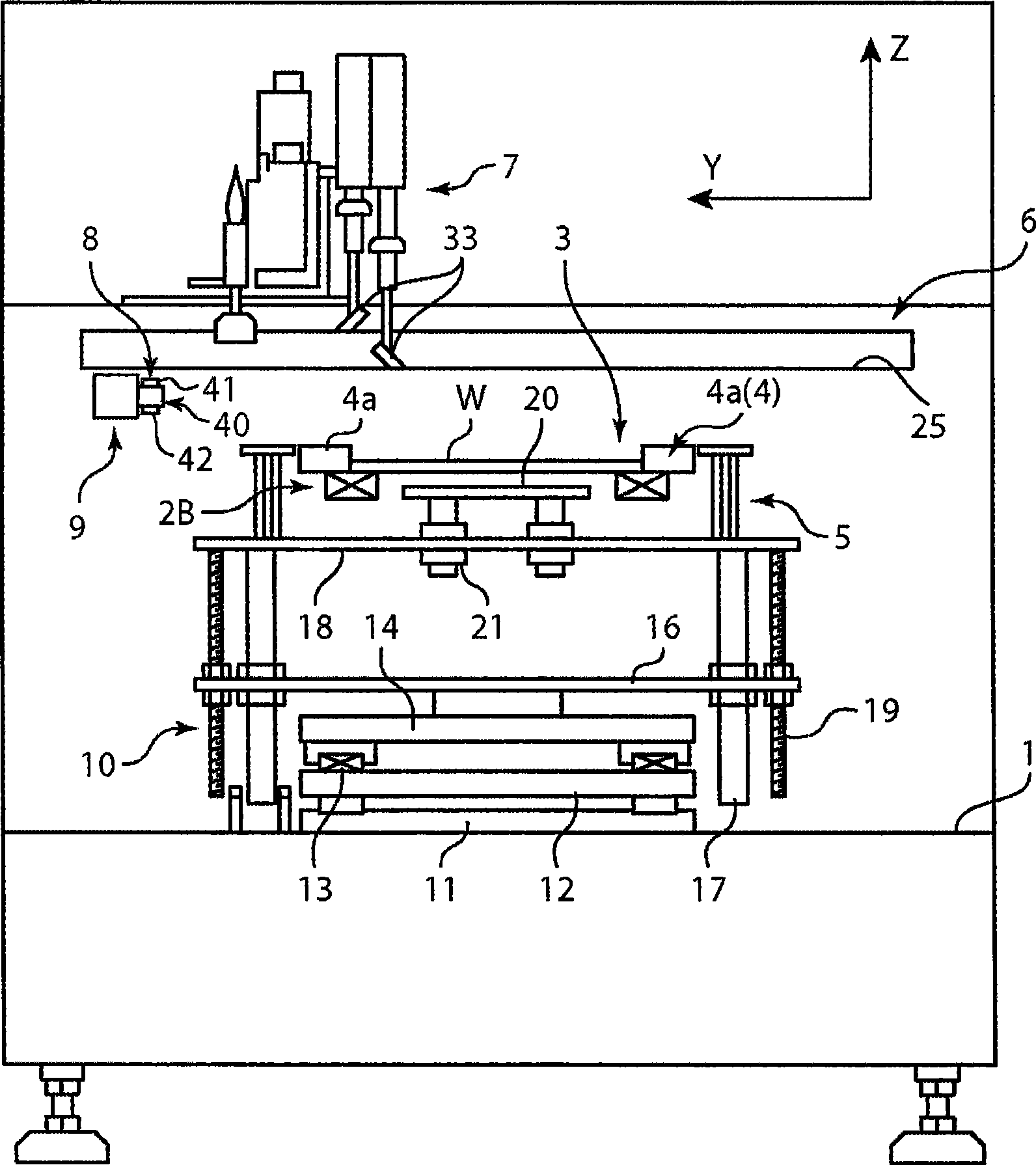
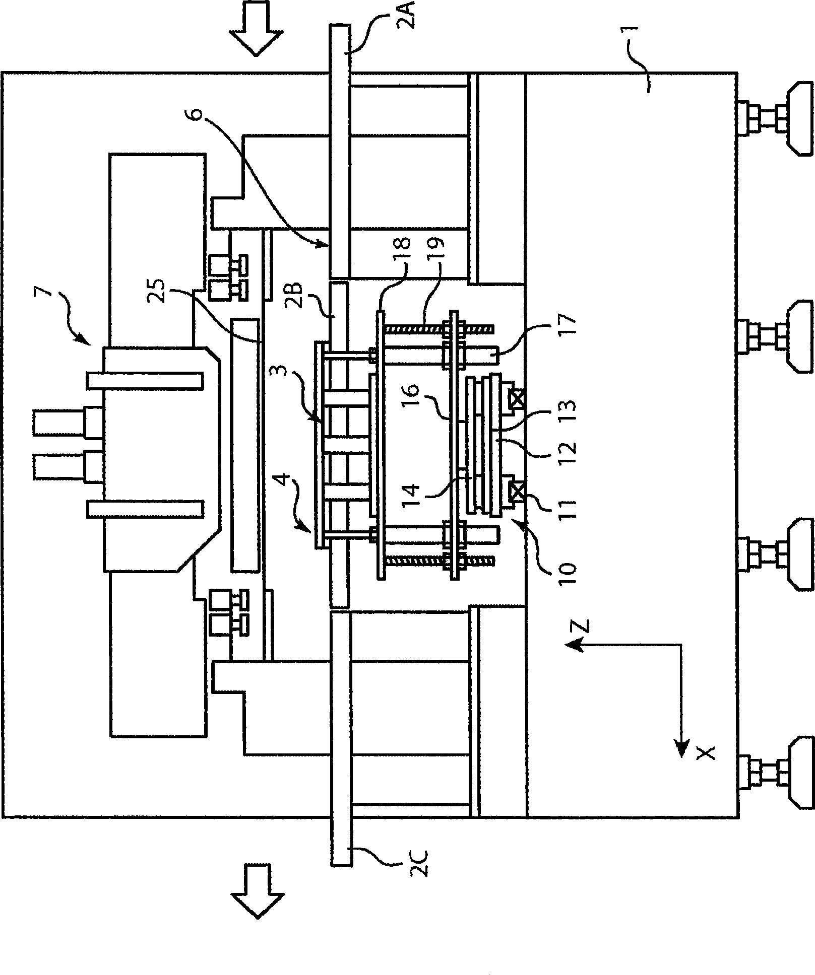
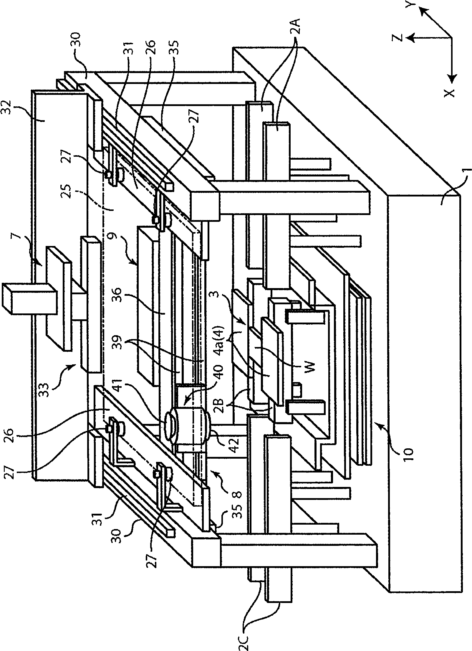
[0025] figure 1 , figure 2 A screen printing device according to the present invention (a screen printing device using the alignment method according to the present invention) is schematically shown, wherein, figure 1 It is a side view of the main part of the screen printing device with the case removed, figure 2 is the main view.

[0026] like figure 1 , figure 2 As shown, on the base 1 of the screen printing device (hereinafter referred to as the printing device), a printing table 3 is arranged, and on both sides of the printing table 3, a printed substrate W (hereinafter referred to as the substrate W) is arranged along the conveying line. ) the upstream conveyor belt 2A carrying it into the printing table 3 and the downstream conveyor belt 2C carrying it out of the printing table 3 .

[0027] In addition, in the following description, the conve...


PUM


Abstract

The invention relates to a position matching method for a screen printing device and a screen printing device. The screen pringting device includes a mask sheet (25), a movable printing stage (3), a camera head (40) having a mask recognition camera (41) and a substrate recognition camera (42), and a controller for controlling them. The controller executes mark recognition of the substrate (W) by using the substrate recognition camera (42). The camera head (40) is driven / controlled so as to execute mask recognition of the mask sheet (25) periodically by using the recognition camera (41) while the same mask sheet is used. Moreover, according to the latest mask position information acquired by the mark recognition of the mask sheet (25) and the substrate position information, the controller obtains a correction amount based on the position shift between the mask sheet (25) and the substrate (W) and drives / controls the printing state (3) according to the correction amount so as to mount the substrate (W) on the mask sheet (25).

Description

technical field [0001] The present invention relates to a screen printing device for printing paste such as paste solder and conductive paste on a substrate. Background technique [0002] Conventionally, there is known a printing apparatus in which a substrate (printed wiring board) placed on a printing table is superposed on a stencil, and a paste such as solder paste or conductive paste supplied on the stencil is pressed by a squeegee. Here, the paste is applied (printed) to predetermined positions on the substrate through openings formed in the template. [0003] In this type of printing apparatus, for example, as described in Japanese Patent Publication No. 2682145, an upward-facing stencil recognition camera is installed on a movable printing table supporting a substrate, and the stencil recognition camera is used to take pictures of the stencils placed on the stencil. For marking, a substrate recognition camera facing downward is fixedly installed on the apparatus fra...

Claims


Application Information

Patent Timeline
Patent Type & Authority Applications(China)
IPC IPC(8): B41F15/26B41F33/14H05K3/12H05K3/34
CPCH05K1/0269B41F15/26H05K3/1216H05K2201/09918H05K2203/166B41P2215/114H05K3/0008
Inventor 相羽昌孝
Owner YAMAHA MOTOR CO LTD
Why Eureka
Try Eureka