Non-contact stationary type fluorescent molecular tomography method and device
A technology of fluorescent molecular tomography and imaging method, which is applied in measurement devices, fluorescence/phosphorescence, material analysis by optical means, etc., can solve problems that affect the survival of experimental animals 111, limit the application of fluorescent molecular tomography, and is difficult to achieve high-throughput Experiments and other issues to achieve the effect of shortening the shooting distance, shortening the exposure time, and improving the quality
- Summary
- Abstract
- Description
- Claims
- Application Information
AI Technical Summary
Problems solved by technology
Method used
Image
Examples
Embodiment 1
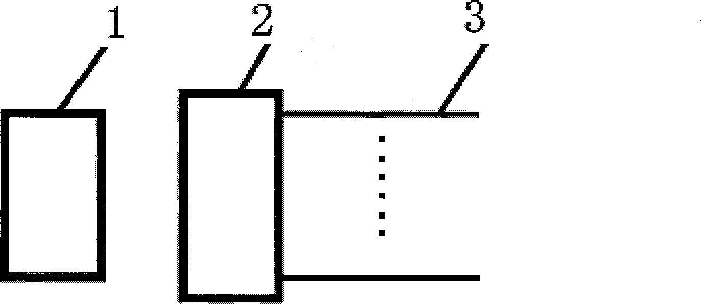
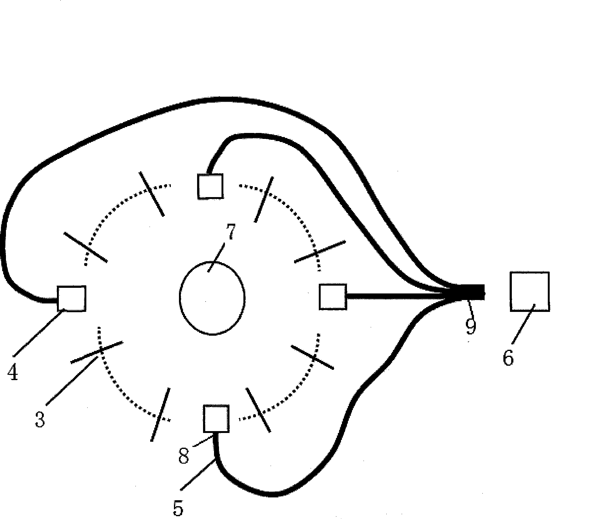
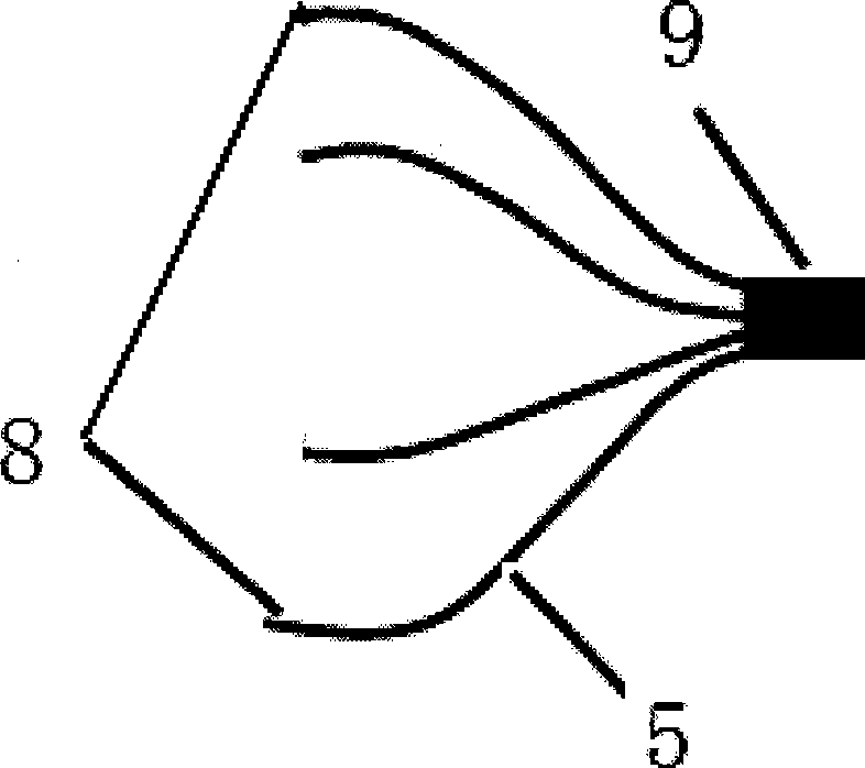
[0028] Such as Figure 4 , Figure 5As shown, the device of this embodiment includes 24 light-transmitting optical fibers 31-324 and 4 optical lenses 41-44 arranged around the object 7 to be measured, and an imaging plane of each optical lens 41-44 is respectively arranged A detector 6 is arranged at the bifurcated end of the image-transmitting optical fiber 5 and the light outlet of the compound end of the image-transmitting optical fiber 51-54; A computer is used to receive instructions from the computer to switch the excitation light to any light-transmitting optical fiber 31-324. An excitation light source 1 is arranged on the light-incoming side of the light switching part 2, and an excitation light filter 10 is arranged on the front end of the light switching part 2, so that the excitation light that can excite the luminescence band of the fluorescent substance in the measured object 7 enters the light switching Part 2, while filtering out other stray light. At the sa...
Embodiment 2
[0032] Such as Image 6 As shown, most of the device of this embodiment is the same as that of Embodiment 1, but the excitation light source 1 in this embodiment adopts a semiconductor laser with a wavelength of 671 nanometers and an output power of 200 milliwatts, so it is not necessary to set the front end of the optical switching component 2 Excitation light filter 10. There are 12 light transmission optical fibers 3 in this embodiment, and there may be more or less. In addition, the fluorescence filters 11 arranged at the front ends of the optical lenses 41 - 44 may not be provided, and only one fluorescence filter 11 is arranged at the front end of the detector 6 .
[0033] When this embodiment is used, firstly, the computer controls the light switching component 2, and the excitation light from the excitation light source 1 is irradiated on the object 7 through any light transmission optical fiber 31-312, and the measured object 7 is irradiated by each optical lens 41-4...
PUM
 Abstract
Description
Claims
Application Information
 - R&D
- Intellectual Property
- Life Sciences
- Materials
- Tech Scout
- Unparalleled Data Quality
- Higher Quality Content
- 60% Fewer Hallucinations
Browse by: Latest US Patents, China's latest patents, Technical Efficacy Thesaurus, Application Domain, Technology Topic, Popular Technical Reports.
© 2025 PatSnap. All rights reserved.Legal|Privacy policy|Modern Slavery Act Transparency Statement|Sitemap|About US| Contact US: help@patsnap.com


