
DLC infrared anti-refiection protective film and method for producing the same

An anti-reflection and protective film technology, applied in sputtering plating, ion implantation plating, coating, etc., can solve the problem of narrow transmission band and achieve less interference, anti-reflection effect and good wear and corrosion resistance , easy to control effects

Inactive Publication Date: 2009-06-24
SICHUAN UNIV
View PDF2 Cites 43 Cited by
  • Summary
  • Abstract
  • Description
  • Claims
  • Application Information

AI Technical Summary

Problems solved by technology

However, the above two patents have the same problem: the transmission band is narrow
There is no patent report on the use of unbalanced magnetron sputtering technology to prepare DLC film as infrared anti-reflection protective film on ZnSe substrate

Method used


Image

  • DLC infrared anti-refiection protective film and method for producing the same
  • DLC infrared anti-refiection protective film and method for producing the same
  • DLC infrared anti-refiection protective film and method for producing the same

Examples


Embodiment (1

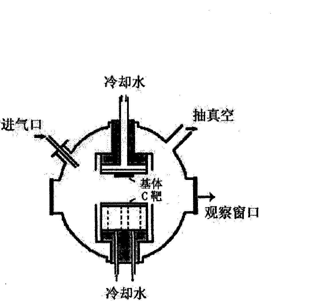
[0019] In the experiment, the intermediate frequency unbalanced magnetron sputtering method was used, and the CH 4 The mixed gas of Ar and Ar is used as discharge gas to deposit DLC bilayer film on ZnSe substrate. The IF frequency used is 40kHz with a duty cycle of 80%. CH 4 and Ar gas are sent into the vacuum chamber from the gas inlet, and the ratio of the two gases is controlled by a needle valve. The vacuum degree during film deposition is 0.1-2Pa by mechanical pump and molecular pump. During deposition, CH 4 The positive ions generated by the ionization of Ar and Ar bombard the graphite target under the action of an electric field, and the sputtered C and CH 4 The hydrocarbon plasma produced by decomposition generates a DLC film on the ZnSe substrate. The ZnSe substrate needs to be pretreated by polishing and cleaning before being placed in the vacuum chamber; after being placed in the vacuum chamber, ion beam sputtering or backsputtering is used to further remove su...

Embodiment (2

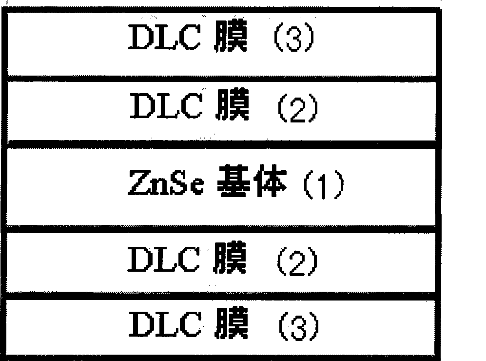
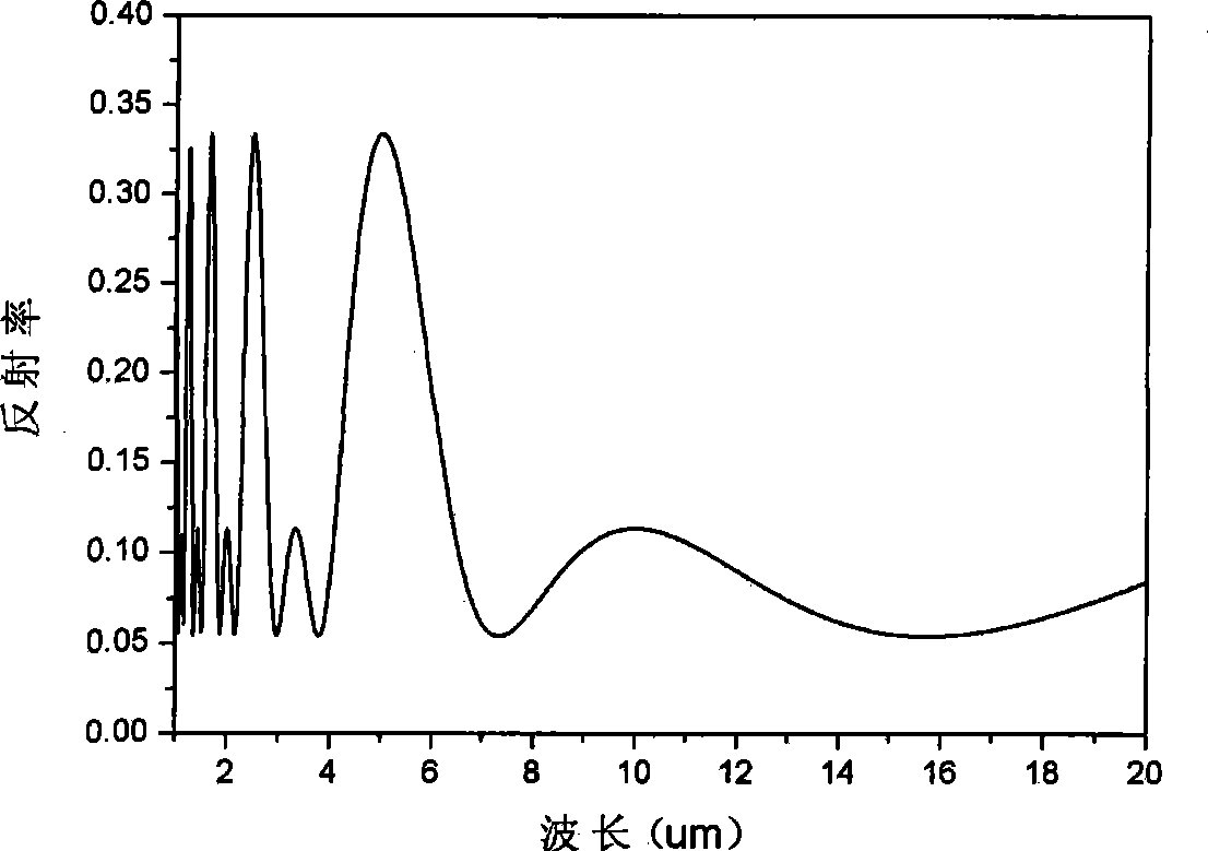
[0022] With 10 μm as the center anti-reflection wavelength, first prepare a high refractive index DLC film 2 with a refractive index of 2.1 on one side of the ZnSe substrate (refractive index 2.5), with a thickness of ~1.2 μm; The DLC film 3 with a ratio of 1.7 has a thickness of ~1.5 μm. The same DLC double-layer film was prepared on the other side of the ZnSe substrate according to the above method. The change curve of reflectivity with wavelength is as follows: Figure 3 Show. Depend on Figure 3 can See, in the wavelength range of 1.0-20 μm, the minimum reflectance of the film system reaches 5.4% (~7.3 μm and 15.7 μm); in the wavelength range of 6.5-20 μm, the reflectance curve is relatively flat, with an average reflectance of 8%, compared with The reflectance before the anti-reflection protective film is not coated is reduced by 25%; the average reflectance is 8% in the wavelength range of 2.7-4.2 μm, which is 25% lower than that before the anti-reflection protective ...

Embodiment (3

[0024] With 10.5 μm as the center anti-reflection wavelength, first prepare a high refractive index DLC film 2 with a refractive index of 2.5 on one side of the Ge substrate (refractive index 4.0), with a thickness of ~1.0 μm; then prepare on the high refractive index DLC film 2 The DLC film 3 with a refractive index of 1.7 has a thickness of ~1.5 μm. The same DLC bilayer film was prepared on the other side of the Ge substrate as described above. The curve of its reflectivity as a function of wavelength is shown in Figure 4 shown. It can be seen from the figure that at ~7.7μm and ~16.5μm, the film system achieves zero reflectivity; the reflectivity of the film system in the wavelength range of 13-21μm is ≤10%; the reflectivity of the film system in the wavelength range of 7.0-23μm ≤20%. The anti-reflection range is wide, and the effect is ideal.


PUM

PropertyMeasurementUnit
refractive indexaaaaaaaaaa
transmittivityaaaaaaaaaa
reflectanceaaaaaaaaaa

Abstract

The invention relates to a DLC infrared anti-reflection protective film and a preparation method thereof. The infrared anti-reflection protective film has the anti-reflection effect at a wider infrared band and simultaneously ensures that an optical element after being filmed has the capacity of abrasion and corrosion resistance. The infrared anti-reflection protective film adopts the structure that a double-layer film is prepared on ZnSe(1); and the refractive index n1 of a first layer of high refractive index film is 1.8 to 2.5, and the thickness d1 thereof is within the scope of about 0.25 Lambada / n1; the refractive index n2 of a second layer of high refractive index film is 0.1 less than that of the first layer of high refractive index film at least, and the thickness d2 thereof is within the scope of about 0.25 Lambada / n (wherein, Lambada is the anti-reflection central wavelength of the infrared anti-reflection film). The preparation method comprises the step of depositing diamond like carbon (DLC) anti-reflection film on double sides or single side of a transparent basal body by adopting the unbalanced intermediate frequency or radio frequency magnetic control sputtering method and taking graphite as a target source, and hydrocarbon and Ar mixed gas or pure Ar as auxiliary discharge gas. Two layers of DLC films with different refractive indexes are prepared through controlling depositing parameters; and the thickness required for each film is obtained through controlling the time. The method has the advantages of convenient control of the depositing parameters of the films, less interference among the depositing parameters, and better anti-reflection effect and abrasion and corrosion resistance.

Description

1. Technical field [0001] The invention relates to a DLC infrared anti-reflection protective film and a preparation method thereof. The infrared anti-reflection protective film is formed on the incident surface or the incident surface and the exit surface of the infrared transparent optical element by the unbalanced magnetron sputtering method, so that the amount of reflected light on the incident surface is reduced. The infrared band has a good anti-reflection effect, and the film layer has the effect of wear resistance and corrosion resistance. 2. Background technology [0002] Anti-reflective coatings have been widely used in the optical field to reduce the reflection of light from the air and the boundaries of optical components. Camera lenses, liquid crystal displays, automotive windows, solar cells, infrared detection, etc. are examples of such applications. [0003] The infrared window is the pre-protection component of the infrared detection of the detector, etc. Z...

Claims


Application Information

Patent Timeline
Patent Type & Authority Applications(China)
IPC IPC(8): G02B1/11C23C14/35C23C14/02C23C14/06C23C14/54G02B1/115
Inventor 黄宁康代海洋陈剑瑄
Owner SICHUAN UNIV
Learn More