
Technique for cooling titanic chloride burner gas

A cooling process, titanium tetrachloride technology, applied in the direction of titanium halide, chemical industry, climate sustainability, etc., can solve the problems of difficult high-temperature furnace gas heat utilization, cumbersome process, and large volume, and achieve environmental protection , Protect the ecological environment, save energy and resources

Active Publication Date: 2009-06-24
GUIYANG AL-MG DESIGN & RES INST
View PDF2 Cites 24 Cited by
  • Summary
  • Abstract
  • Description
  • Claims
  • Application Information

AI Technical Summary

Problems solved by technology

So far, my country mainly uses ilmenite (TiFeO 3 ) into high titanium slag (TiO 2 ), and then in the chlorination furnace, add oil coke, and pass chlorine gas to generate thick titanium tetrachloride (TICl 4 ), but also generate a large amount of high-temperature furnace gas. The existing domestic furnace gas treatment process equipment is bulky, heavy (sedimentation chamber), backward in technology, and difficult to control the temperature; Natural rutile is imported, but the cooling and condensing system of the boiling chlorination system is still a backward process, which cannot make full use of energy to achieve the purpose of energy saving and emission reduction
[0003] In the prior art, Chinese patent application No. 200510022528.X discloses a waste heat utilization method after the fluidized furnace in sulfuric acid production. Although this process utilizes the waste heat of the furnace gas, it uses high-temperature flue gas to heat the air, and then uses the air to heat Water and cold air, instead of directly heating water and cold air with high-temperature furnace gas, the process is cumbersome, and it is difficult to make good use of the heat in the high-temperature furnace gas
The Chinese patent application number 89102481.6 discloses a dry purification method for furnace gas. In this method, the cooling and condensing system of the furnace gas is outdated and cannot be well applied to the sufficient cooling of titanium tetrachloride furnace gas and energy saving and emission reduction.

Method used


Image

  • Technique for cooling titanic chloride burner gas

Examples


Embodiment

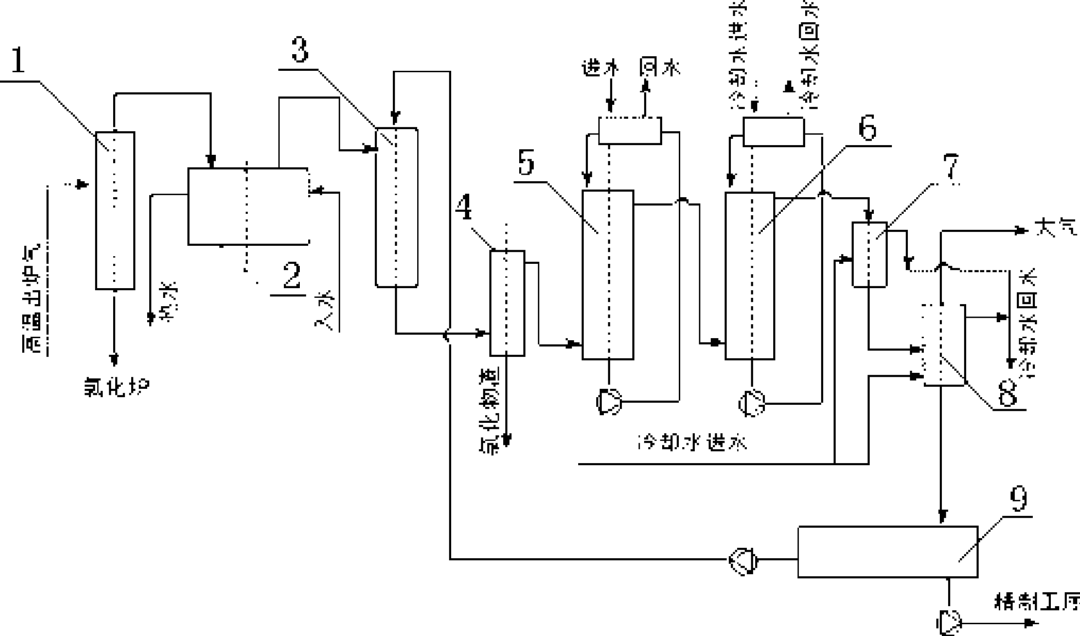
[0015] Embodiment: The temperature of titanium tetrachloride out of the furnace is about 950°C-650°C and contains dust. It first enters the cyclone dust collector 1 for dust removal, and the dust returns to the chlorination furnace to continue chlorination. High temperature gas enters 1 after exiting cyclone dust collector 1 # Cooler 2 cools the gas down to 400°C, 1 # The cooler 2 can be cooled with a water jacket to obtain hot water, so that heat energy can be recycled. The gas from the furnace enters the spray condensation tower 3 sprayed with crude titanium tetrachloride. The thick titanium tetrachloride sprayed into the spray condensation tower 3 is evaporated, so that the temperature of the discharged gas is reduced to 180-171°C. 3 Those with similar boiling points (315°C) (ZrCl 4 , CrCl 3 , NbCl 5 , AlCl 3 etc.) can become solid between 400~171℃. Then the chloride slag is removed through the bag filter 4. Cleaner gas (containing TiCl 4 、SiCl 4 , VoCl 3 , CO, C...


PUM


Abstract

The invention provides a process for cooling titanium tetrachloride furnace gas, which comprises the following steps: furnace gas discharged sequentially enters a cyclone dust extractor (1) for dust removal, a first cooler (2) for cooling, a spray condensing tower (3) for cooling, a bag filter (4) for filtering, a front leaching tower (5), a rear leaching tower (6), a second cooler (7) for further condensation and a cooling drum (8); waste gases discharged from the cooling drum enter a tail gas washing system and are discharged into the air after meeting discharge standards; and liquid enters a coarse titanium tetrachloride tank (9). The process reasonably uses the heat of the high-temperature titanium tetrachloride furnace gas, improves the recovery rate of TiCl4, reduces the discharge of harmful gases in the tail gas, contributes to environment production, and meets the requirements for establishing an industrial structure which is energy and resource-saving and ecological environment-friendly.

Description

technical field [0001] The invention relates to a cooling process of furnace gas, in particular to a cooling process of titanium tetrachloride furnace gas. Background technique [0002] Titanium tetrachloride is a widely used chemical raw material, which can be used to prepare organic titanium compounds, titanium-containing electronic ceramics, titanium oxide gemstones, etc. In addition, it also has special uses in glass, hard alloy, leather, printing and dyeing industries, etc. So far, my country mainly uses ilmenite (TiFeO 3 ) into high titanium slag (TiO 2 ), and then in the chlorination furnace, add oil coke, and pass chlorine gas to generate thick titanium tetrachloride (TICl 4 ), but also generate a large amount of high-temperature furnace gas. The existing domestic furnace gas treatment process equipment is bulky, heavy (sedimentation chamber), backward in technology, and difficult to control the temperature; Natural rutile is imported, but the cooling and condensi...

Claims


Application Information

Patent Timeline
Patent Type & Authority Applications(China)
IPC IPC(8): C01G23/02B01D53/34
CPCY02P20/10
Inventor 丁子文
Owner GUIYANG AL-MG DESIGN & RES INST
Learn More