
Metal blade forming machine

A technology for metal blades and forming machines, which is applied in metal processing equipment, feeding devices, positioning devices, etc., and can solve the problems of easy deformation of the blade curvature, unbalanced length, and low processing efficiency

Active Publication Date: 2009-06-03
宁波朗迪智能机电有限公司
View PDF0 Cites 13 Cited by
  • Summary
  • Abstract
  • Description
  • Claims
  • Application Information

AI Technical Summary

Problems solved by technology

The defects of the existing equipment are: the semi-automatic operation is adopted, the processing efficiency is low, the radian of the blade after profiling is easily deformed, and the truncated length cannot be uniform in size

Method used


Image

  • Metal blade forming machine
  • Metal blade forming machine
  • Metal blade forming machine

Examples


Embodiment Construction

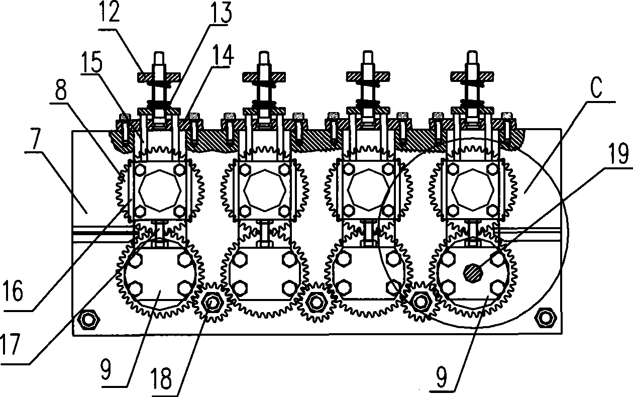
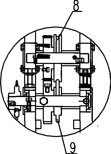
[0023] Attached below Figure 1-6 A detailed description will be made to the specific embodiment of the present invention.

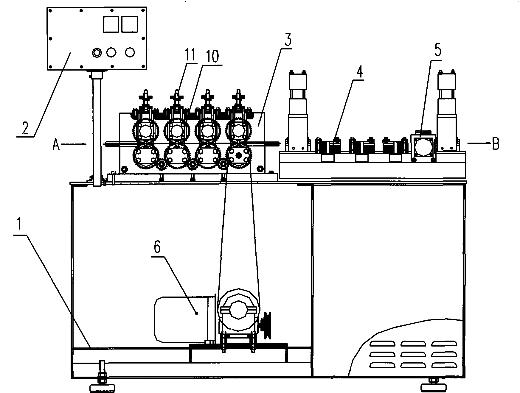
[0024] Such as Figure 1-6 The metal blade forming machine shown is composed of a feeder, a frame 1, a motor 6, and an automatic control device 2, a rolling forming mechanism 3, a cutting mechanism 4 and a throwing mechanism arranged on the frame from left to right. Material mechanism 5. The feeder sends the sheet metal to the roll forming mechanism.

[0025] The rolling forming mechanism 3 consists of side plates 7, 4 sets of profiling wheels 10 arranged horizontally from left to right, and 4 sets of pressing devices 11 corresponding to the number of profiling wheels 10 and arranged above it. The profiled wheel set 10 is composed of a profiled concave wheel 8 with an arc-shaped groove and a profiled cam 9 with an arc-shaped protruding head matched therewith. Adjacent profiling wheel sets 10 are connected by intermediate wheels 18 to ensure that all ...


PUM


Abstract

The invention relates to a metal blade forming equipment used for processing heating and ventilating equipment. A metal blade forming machine comprises a frame (1), a motor (6) and a rolling forming mechanism (3), a material cutting mechanism (4) and a material throwing mechanism (5) which are arranged on the frame. The blade forming machine adopts fully-automatic operation and has high processing efficiency; the rolling forming mechanism ensures that the radians of a profiled blade are consistent, and the whole blade does not flex easily; the material cutting mechanism ensures the standard of the cut blade length and size; and the material throwing mechanism ensures the consistency and the high speed for outputting the formed blade.

Description

technical field [0001] The invention relates to a forming device for processing metal blades used in heating and ventilation equipment. Background technique [0002] Metal blades have an arc-shaped cross-section and are commonly used components in HVAC equipment. For example, a cross-flow fan is composed of multiple metal blades arranged along the grooves on the circumference of the flange. The existing metal blade molding is divided into two steps: forming and cutting. First, the metal blade is pressed with a pressure wheel device to press out the required radian, and then the pressed blade is taken out and placed on a punching machine to cut off. The cut length is manually controlled. . The defects of the existing equipment are: the semi-automatic operation is adopted, the processing efficiency is low, the radian of the blade after profiling is easily deformed, and the truncated length cannot be uniform in size. Contents of the invention [0003] The object of the pres...

Claims


Application Information

Patent Timeline
IPC IPC(8): B21D53/78B21D28/00B21D43/00
Inventor 高炎康黄其全吴大学
Owner 宁波朗迪智能机电有限公司
Learn More