Capsule medical device and body-tissue obtaining method

A medical device and living tissue technology, applied in medical science, in vivo radio detector, inoculation and ovulation diagnosis, etc., can solve the problems of difficult collection of living tissue blocks, difficult brush collection of living tissue blocks, and inability to collect living tissue blocks, etc., to achieve Increased cutting force, reliable cutting and collection effect

Inactive Publication Date: 2009-06-03
OLYMPUS CORP
View PDF2 Cites 14 Cited by
  • Summary
  • Abstract
  • Description
  • Claims
  • Application Information

AI Technical Summary

Problems solved by technology

[0006] However, in the above-mentioned existing capsule medical device, when the living tissue inside the subject is collected, the stroke of the forceps entering and leaving the capsule housing is limited by the size of the capsule housing (small enough to be introduced into the subject). internal size) is limited in a narrow range, it is difficult to cut and collect a block-shaped living tissue (hereinafter referred to as a biopsy block) from the internal part of the subject with the forceps whose stroke is limited, and therefore, there is a possibility that the collection From biopsy blocks of the size required for biopsy such as pathological diagnosis
[0007] Furthermore, in the capsule medical device disclosed in Patent Document 1, even when the brush is rotated by interacting with a rotating magnetic field from the outside, at most cells such as mucous membranes are adhered to the brush for collection, and it is difficult to collect them from the brush. collection of biopsy blocks
In addition, in the capsule medical device disclosed in Patent Document 1, even when the forceps are opened and closed by interacting with a rotating magnetic field from the outside, it is difficult to collect a mass of living tissue only by opening and closing the forceps.

Method used


Image

  • Capsule medical device and body-tissue obtaining method
  • Capsule medical device and body-tissue obtaining method
  • Capsule medical device and body-tissue obtaining method

Examples


Embodiment approach 1

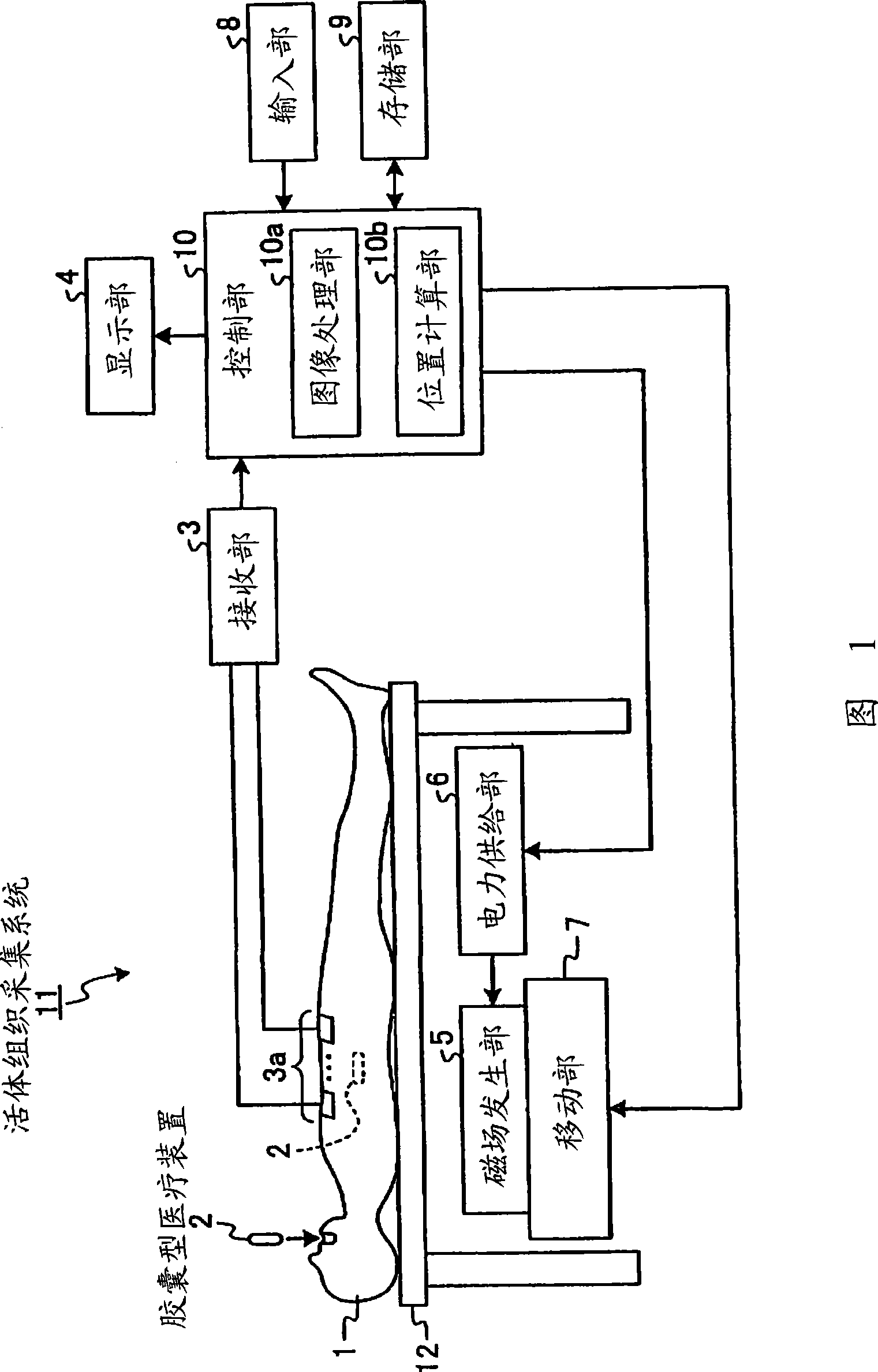
[0070] FIG. 1 is a block diagram schematically showing a configuration example of a biological tissue collection system according to Embodiment 1 of the present invention. The living tissue collection system 11 according to Embodiment 1 is a system for introducing a capsule medical device into a subject, and collecting a mass of living tissue from a desired site in the subject with the introduced capsule medical device. Specifically, as shown in FIG. 1 , the biopsy collection system 11 includes a capsule medical device 2 that is introduced into the inside of a subject 1 such as a patient, and is used to collect samples from the inside of the subject 1 . The receiving unit 3 receives information transmitted from the capsule medical device 2 through the antenna 3a; the display unit 4 displays the in-vivo image of the subject 1 captured by the capsule medical device 2 . In addition, the living tissue collection system 11 has: a magnetic field generator 5 that generates a magnetic...

Embodiment approach 2

[0166] Embodiment 2 of the present invention will be described below. In Embodiment 1 and Modification 1 above, the cutting part is fixed to the capsule-shaped housing, and the cutting part is rotated in the circumferential direction together with the capsule-shaped housing to cut and collect the mass of living tissue from the internal body. In Embodiment 2, the cutting part is rotated in the circumferential direction inside the capsule-shaped casing, and the mass of living tissue sucked into the capsule-shaped casing is cut and collected from the internal body by the cutting part inside the casing.

[0167] Fig. 18 is a schematic diagram showing a configuration example of a capsule medical device according to Embodiment 2 of the present invention. Figure 19 It is a schematic sectional view of C-C of the capsule medical device shown in FIG. 18 . In addition, in FIG. 18 , in order to facilitate description of the internal structure of the capsule medical device according to E...

Embodiment approach 3

[0189] Embodiment 3 of the present invention will be described below. In the above-mentioned second embodiment, a part of the internal body part is taken into the inside of the capsule-shaped casing 60 by the suction force of the suction pump 66, but in the present embodiment 3, the suction pump 66 rotates in the circumferential direction of the capsule-shaped casing. The hook takes a part of the internal part into the capsule-shaped casing.

[0190] Fig. 22 is a schematic diagram showing a configuration example of a capsule medical device according to Embodiment 3 of the present invention. Figure 23 It is a schematic sectional view of D-D of the capsule medical device shown in FIG. 22 . In addition, in FIG. 22 , in order to facilitate description of the internal structure of the capsule medical device according to Embodiment 3, the capsule medical device is shown partially cut away.

[0191] As shown in FIGS. 22 and 23 , the capsule medical device 72 of the third embodimen...


PUM


Abstract

The present invention provides a capsule medical device and a body-tissue obtaining method, capable of collecting a mass of body tissue from the in-vivo region of a subject. The capsule medical device (2) includes a capsule-shaped casing (20) that can be introduced into an in-vivo region of a subject (1); and a rotation driving unit (24) that generates torque along a circumferential direction of the capsule-shaped casing (20). The capsule medical device (2) also includes a cutting-obtaining unit (20c) that rotates along the circumferential direction of the capsule-shaped casing (20) due to the torque to cut out and obtain a mass of body tissue from the in-vivo region of the subject (1).

Description

technical field [0001] The present invention relates to a capsule medical device which is introduced into a subject and is used to collect a biotissue mass of a site to be examined by biopsy such as pathological diagnosis. Background technique [0002] Conventionally, in the field of endoscopes, there have been capsule-type medical devices that are introduced into internal organs of a subject to capture images of the internal organs (hereinafter sometimes referred to as in-vivo images). This capsule-type medical device has an imaging function and a radio communication function for taking pictures inside the capsule-shaped casing, and after being orally administered into a subject such as a patient, it sequentially takes pictures of the subject while moving in the digestive tract due to peristaltic motion or the like. The in-vivo images of the subject are sequentially transmitted by radio to a receiving device outside the subject each time. Furthermore, the capsule medical d...

Claims


Application Information

Patent Timeline
Patent Type & Authority Applications(China)
IPC IPC(8): A61B5/07A61B1/00A61B10/04
CPCA61B10/0283A61B5/061A61B1/041A61B10/0266A61B1/00016A61B5/073A61B10/0275A61B10/04A61B17/00234A61B2019/2253A61B1/00158A61B1/00036A61B19/5225A61B2010/0225A61B10/0096A61B34/73A61B90/37
Inventor 田中慎介
Owner OLYMPUS CORP
Why Eureka
Try Eureka