Rotary knife and method for manufacturing rotary knife
A technology of rotating knife and rotating direction, applied in metal processing and other directions, can solve the problems of the rotating knife lacking water stirring ability, unable to completely remove the attachments, unable to rotate the shaft to stir water, etc., to simplify the structure, increase the water flow, improve the The effect of removing the function
- Summary
- Abstract
- Description
- Claims
- Application Information
AI Technical Summary
Problems solved by technology
Method used
Image

Examples
Embodiment 1
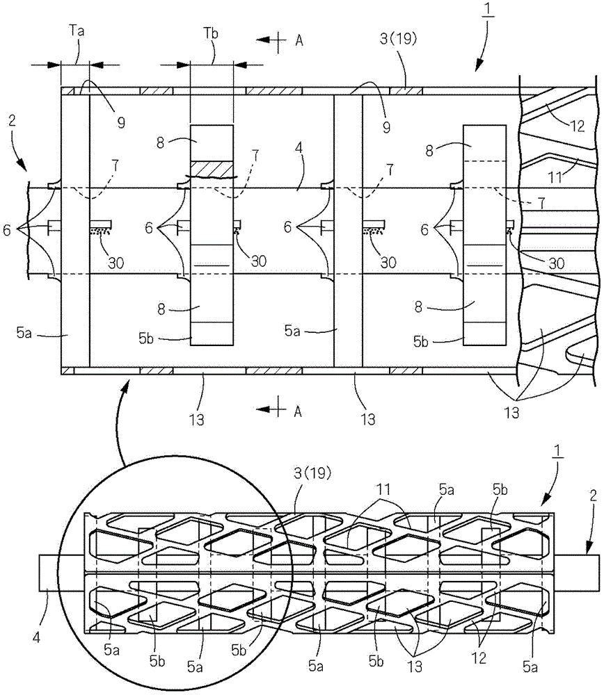
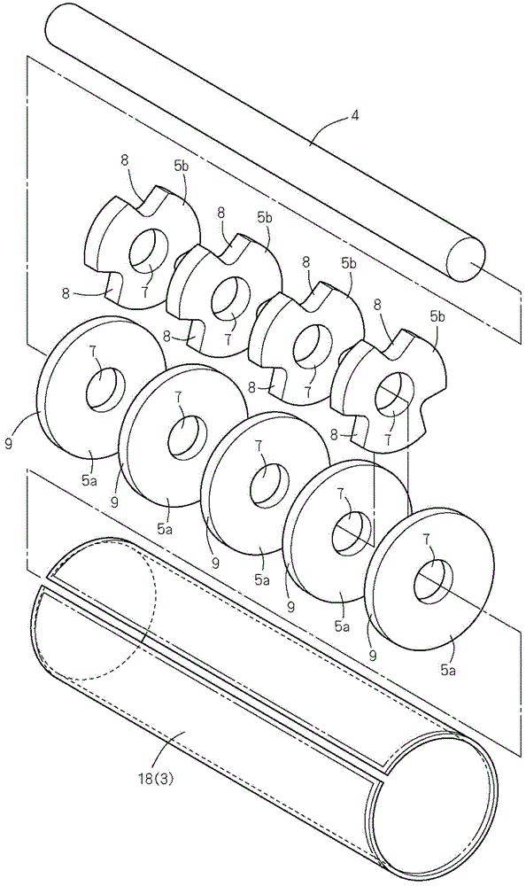
[0093] Figure 1 to Figure 10 Embodiment 1 of the rotary knife of this invention is shown. exist figure 1 and figure 2 Among them, the rotary blade 1 is composed of a rotary shaft body 2 and a cylindrical cutting blade 3 fixed on the rotary shaft body 2 . The rotating shaft body 2 is composed of a shaft main body 4, five supporting discs 5a and four water flow generating discs 5b which are pressed and fixed on the shaft main body. The supporting discs 5a and the water flow generating discs 5b are alternately arranged along the rotation axis direction.
[0094] The shaft main body 4 is a round shaft-shaped martensitic stainless steel material. The support disk 5 a is formed in a disk shape by punching a plate made of austenitic stainless steel material, and a charging hole 7 through which the shaft main body 4 is inserted is formed at the center thereof. Such as image 3 As shown, the peripheral surface of the supporting disk 5a becomes the blade supporting surface 9 for...
Embodiment 2
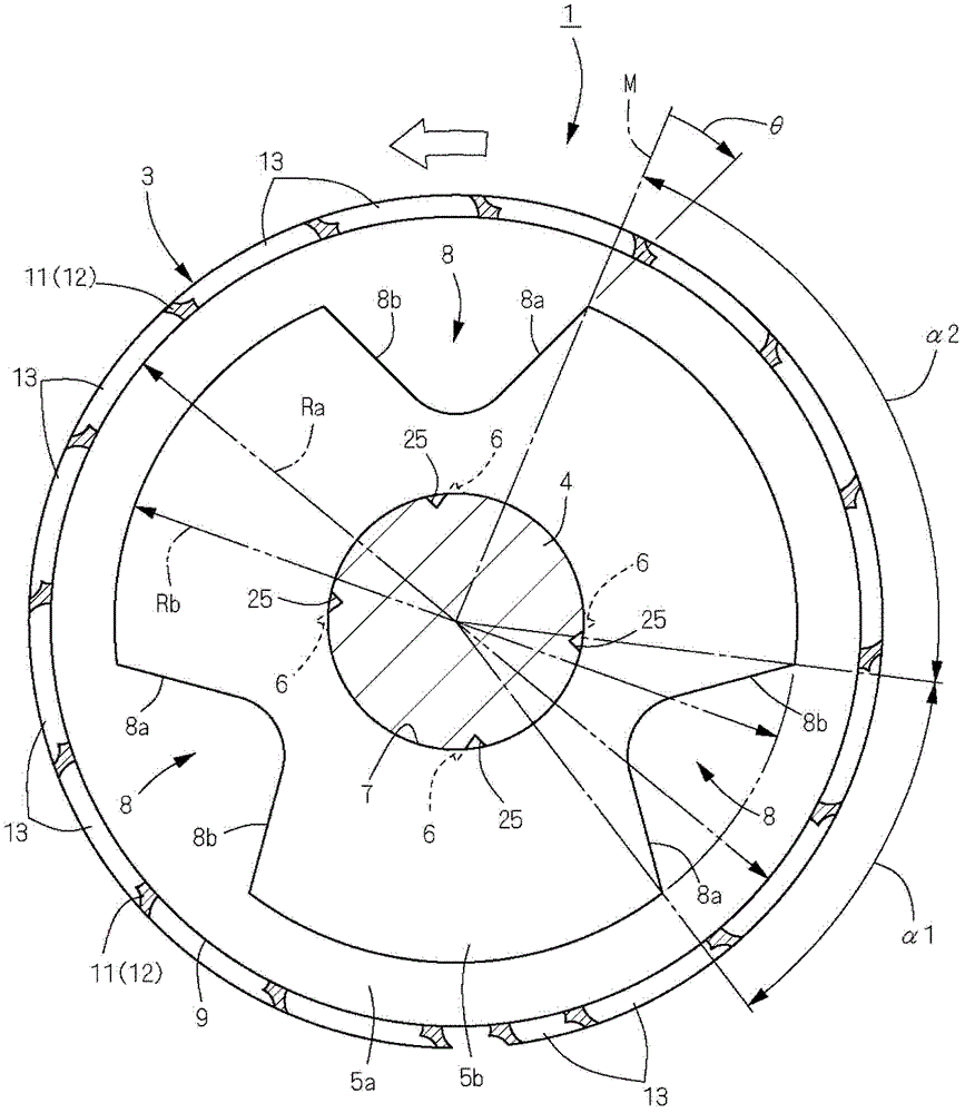
[0125] Figure 11 ~ Figure 13 A second embodiment in which the structure of the rotating shaft body 2 is different is shown. Here, a water flow generating portion 8 and a blade supporting surface 9 are formed on each of the five discs 5 press-fitted and fixed to the shaft main body 4 . Specifically, water flow generating portions 8 made of V-shaped slits are formed at equal intervals at three positions on the peripheral surface of the disk 5, and the peripheral surface sandwiched by the water flow generating portions 8, 8 is used as a knife supporting surface 9. . That is, the disk 5 of this embodiment has both the functions of the supporting disk 5a and the water flow generating disk 5b of the first embodiment above. The disk 5 can be manufactured by the same method as the water flow generating disk 5b of the first embodiment above.
[0126] Such as Figure 13 As shown, the water flow generation part 8 is shifted in phase in the circumferential direction with respect to t...
Embodiment 3
[0128] Figure 14 and Figure 15 It shows the third embodiment in which the structure of the rotating shaft body 2 is different. The rotary shaft body 2 here is constituted by a turned product made of stainless steel (made of metal) integrally provided with the shaft main body 4 , the supporting disc 5 a and the water flow generating disc 5 b. However, the water flow generating portion 8 of the water flow generating disk 5b is formed by broaching. A concave curved surface 46 concaved toward the center of rotation is formed on the peripheral surface of the shaft main body 4 between the adjacent supporting disk 5a and the water flow generating disk 5b.
PUM
 Abstract
Description
Claims
Application Information
 - R&D
- Intellectual Property
- Life Sciences
- Materials
- Tech Scout
- Unparalleled Data Quality
- Higher Quality Content
- 60% Fewer Hallucinations
Browse by: Latest US Patents, China's latest patents, Technical Efficacy Thesaurus, Application Domain, Technology Topic, Popular Technical Reports.
© 2025 PatSnap. All rights reserved.Legal|Privacy policy|Modern Slavery Act Transparency Statement|Sitemap|About US| Contact US: help@patsnap.com