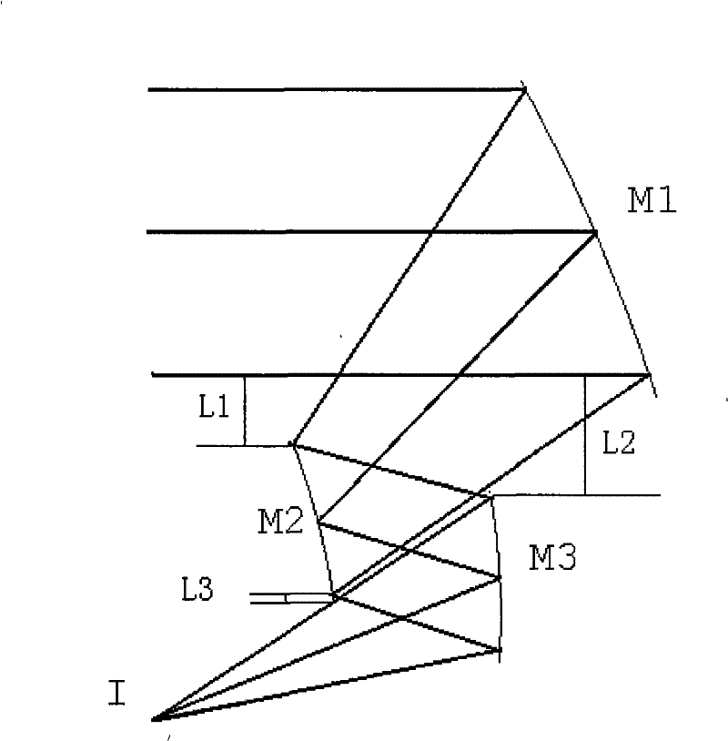
Non-barrier three-reflector optical system
A technology of three mirrors and an optical system, applied in the field of optical systems, to achieve the effect of reducing free variables, increasing design difficulty, and increasing free variables
- Summary
- Abstract
- Description
- Claims
- Application Information
AI Technical Summary
Problems solved by technology
Method used
Image
Examples
Embodiment 1
[0053] See attached figure 2 , which is a structural schematic diagram of the optical system of the present embodiment; wherein, M1 is the primary mirror, M2 is the secondary mirror, M3 is the third mirror, I is the image plane, and L1 is for avoiding obstruction, the lowermost edge light of M1 and the light of M2 The distance of the uppermost edge ray in the direction perpendicular to the optical axis, L2 is the distance between the lowermost edge ray of M1 and the uppermost edge ray of M3 in the direction perpendicular to the optical axis when avoiding occlusion, and L3 is the distance between the uppermost edge ray of M1 and M2 when avoiding occlusion The distance between the lower edge ray and the uppermost edge ray of M3 in the direction perpendicular to the optical axis.
[0054] The relative aperture D / f of the system is 1, the focal length is 360mm, and the field of view is 3°×0.02°. The system is off-axis to avoid obstruction; the optical path of the system is the t...
Embodiment 2
[0067] See attached Image 6 , which is a structural schematic diagram of the optical system of this embodiment; wherein M1 is the primary mirror, M2 is the secondary mirror, and M3 is the third mirror. The focal length is 360mm, the relative aperture of the system is 1 / 2.4, and the field of view is 3°×0.02°.
[0068] The aperture of the system is on the secondary mirror, the secondary mirror M2 is on the focal plane of the triple mirror M3, the image side is telecentric, the distance between the rear working distance image plane I and the secondary mirror M2 is 80mm, and the system structure size is about 280mm(z) ×240mm(y)×150mm(x). L1, L2, and L3 are 10mm, 10mm, and 10mm, respectively. Each mirror radius approximately satisfies the Petswan condition. The three mirrors are all Zernike free-form surfaces. The specific structural parameters and Zernike polynomial coefficients of the system are listed in Table 4 through the optimization design of the optical design software....
Embodiment 3
[0079] See attached Figure 10 , which is a structural schematic diagram of the optical system of this embodiment. Among them, M1 is the primary mirror, M2 is the secondary mirror, and M3 is the third mirror. The focal length is 360mm, the relative aperture D / f is 1 / 2.4, and the field of view is 3°×2°.
[0080] The secondary mirror M2 is on the focal plane of the three-mirror M3, the image side is telecentric, the rear working distance is 80mm from the image plane I to the secondary mirror M2, and the system structure size is about 800mm(z)×240mm(y)×150mm( x). L1, L2, L3 are 20mm, 30mm, 10mm respectively. The radius of each surface approximately satisfies the Petzwan condition. The three mirrors are all Zernike free-form surfaces, and the aperture is on the secondary mirror. The optical design software optimizes the design, and the specific structural parameters and Zernike polynomial coefficients of the system are listed in Table 6.
[0081] Table 6: System structure par...
PUM
 Abstract
Description
Claims
Application Information
 - R&D
- Intellectual Property
- Life Sciences
- Materials
- Tech Scout
- Unparalleled Data Quality
- Higher Quality Content
- 60% Fewer Hallucinations
Browse by: Latest US Patents, China's latest patents, Technical Efficacy Thesaurus, Application Domain, Technology Topic, Popular Technical Reports.
© 2025 PatSnap. All rights reserved.Legal|Privacy policy|Modern Slavery Act Transparency Statement|Sitemap|About US| Contact US: help@patsnap.com


