
Colored filter board

A color filter and filter technology, applied in optics, optical components, nonlinear optics, etc., can solve problems such as environmental pollution, high cost of chrome-plated metal film layers, and prolonged production cycle, and achieve the goal of reducing production costs Effect

Inactive Publication Date: 2009-05-13
SHANGHAI SVA LIQUID CRYSTAL DISPLAY
View PDF0 Cites 17 Cited by
  • Summary
  • Abstract
  • Description
  • Claims
  • Application Information

AI Technical Summary

Problems solved by technology

At present, the black matrix formed by using the heavy metal chromium (Cr) is the mainstream, but it has the following disadvantages: the cost of the chrome-plated metal film layer is high; the reflectivity of the chromium metal film layer is high; the black matrix pattern (pattern) produced Environmental Pollution by Wastes of Heavy Metal Chromium
The black matrix formed by electroless nickel plating has the following disadvantages: high opacity (high optical density); low reflectivity in the visible wavelength range
In terms of process, the color filter plate based on the existing technology needs to specially manufacture a layer of black matrix, so the production cycle will be lengthened, and the existence of this process will also increase the cost of the color filter plate.

Method used


Image

  • Colored filter board
  • Colored filter board
  • Colored filter board

Examples


Embodiment Construction

[0018] The color filter plate of the present invention will be further described in detail with reference to the accompanying drawings.

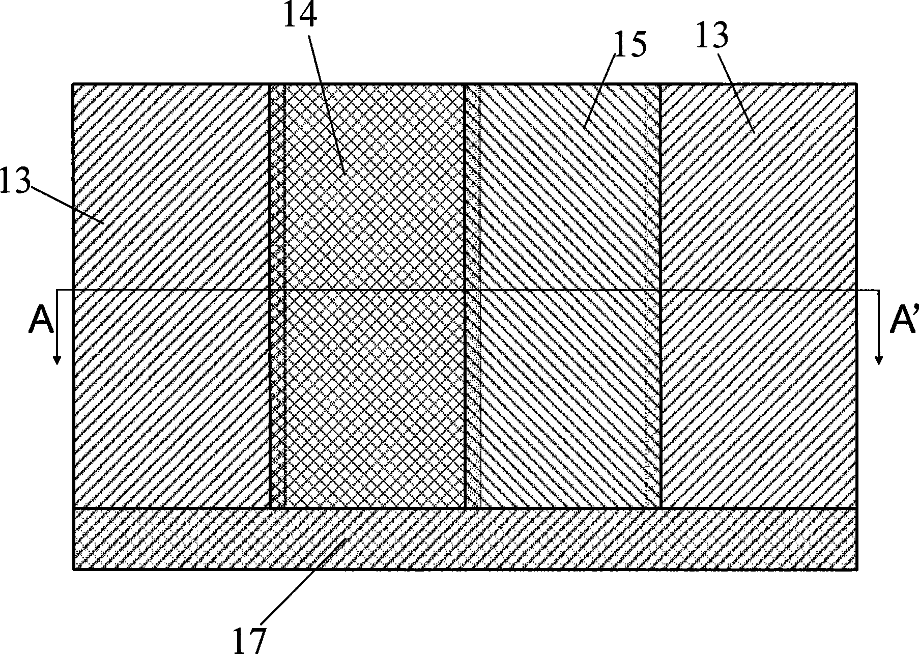
[0019] figure 2 It is a structural schematic diagram of the color filter plate of the first embodiment of the present invention, image 3 for along figure 2 A-A'direction sectional view. like figure 2 , image 3 As shown, the color filter plate of the first embodiment of the present invention includes: a glass substrate 11; a blue color filter 13, formed on the glass substrate 11; a red color filter 14, when necessary The shading area overlaps with the blue filter 13; a green filter 15 is formed between the blue filter 13 and the red filter 14; a cover layer 16 is used to carry out the above-mentioned each filter flattening treatment. Because in the area where the red filter 14 overlaps with the blue filter 13, the total film thickness is larger than the film thickness of the non-overlapping area, in order to ensure that the steps o...


PUM

PropertyMeasurementUnit
thicknessaaaaaaaaaa

Abstract

The invention relates to a color filter plate which comprises a glass substrate, a blue light filter and a red light filter which is formed on the glass substrate, wherein, the red light filter is partially overlapped with the blue light filter to form a shading region. The color filter plate does not need a manufacturing process of a black matrix in a black filter plate, and lower the production cost of the color filter plate.

Description

technical field [0001] The invention relates to a color filter plate, in particular to a color filter plate without a black matrix. Background technique [0002] The color filter is mainly composed of red (R), green (G), blue (B) pixels that can represent full colors, and a black matrix (Black Matrix) that improves pixel contrast. In the production of Thin Film Transisitor Liquid Cyrstal Display (TFT-LCD) panels, in order to maintain the uniformity of the interval between the color filter plate and the glass substrate, it is also necessary to make photosensitive spacers on the color filter plate ( Photo Spacer). The schematic diagram of the color filter plate structure is as follows figure 1 As shown, it includes a glass substrate 1, a blue color filter 3, a red color filter 4, a green color filter 5 positioned on the glass substrate 1, and a black matrix 2 positioned between the above-mentioned three color filters, The cover layer 6 located on the above-mentioned three-c...

Claims


Application Information

Patent Timeline
Patent Type & Authority Applications(China)
IPC IPC(8): G02B5/23G02F1/1335
Inventor 马群刚
Owner SHANGHAI SVA LIQUID CRYSTAL DISPLAY
Learn More