
Large scale stalk anaerobic fermentation technique and apparatus

An anaerobic fermentation, large-scale technology, applied in the direction of fermentation, fertilization equipment, biochemical cleaning equipment, etc., can solve the problems of non-continuous gas production, no fluidity, low straw density, etc., achieve low cost and reduce waste gas emissions , good effect

Inactive Publication Date: 2009-04-15
SHANDONG UNIV
View PDF1 Cites 14 Cited by
  • Summary
  • Abstract
  • Description
  • Claims
  • Application Information

AI Technical Summary

Problems solved by technology

In the current research, it is agreed that straw has low density, large volume, and no fluidity. Therefore, it is impossible to use a general "continuous flow" reactor.
However, the current "batch" reactor needs to be completely shut down to load and unload materials, the operation period is long, and it cannot produce gas continuously and stably

Method used


Image

  • Large scale stalk anaerobic fermentation technique and apparatus

Examples


Embodiment 1

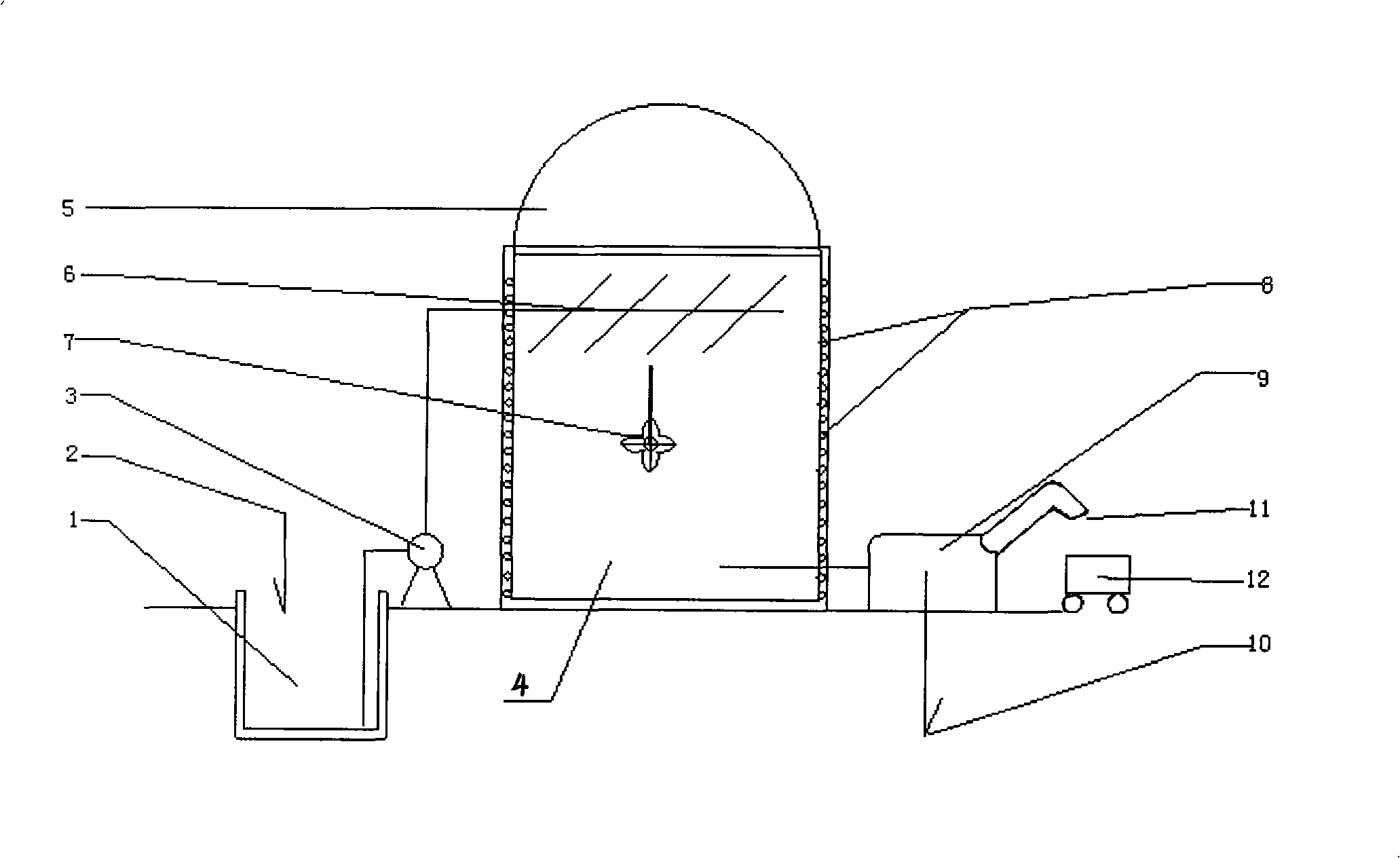
[0039] Anaerobic fermentation device, structure such as figure 1 As shown, the anaerobic bacteria liquid return port 2 is provided on the material tank 1, the raw materials in the material tank enter the anaerobic generator 4 through the pump 3, the top of the anaerobic generator 4 has a rubber storage air bag 5, and the anaerobic generator 4 There is a distributing device 6 on the upper part, the stirring device 7 is located in the middle of the anaerobic generator 4, the steam heating tube coil 8 is coiled on the wall of the anaerobic generator 4, and the outer part is an insulation layer. The lower part of the anaerobic generator 4 is connected to the anaerobic bacteria separation device 9, the bottom of the anaerobic bacteria separation device 9 has an anaerobic bacteria liquid outlet 10, and the upper part of the anaerobic bacteria separation device 9 has a straw organic fertilizer output nozzle 11, which outputs straw organic fertilizer. Below the nozzle 11 is a receiving ca...

Embodiment 2

[0040] Embodiment 2: A large-scale anaerobic fermentation process of straw, which is carried out using the device of embodiment 1, and the steps are as follows:

[0041] (1) Straw pretreatment

[0042] White rot fungi is added to the straw, stacked for 5 days, and naturally fermented to obtain biologically treated straw.

[0043] (2) Anaerobic fermentation

[0044] Crush the biologically treated straw in step (1) to 4-5mm, put it into tank 1, send it to anaerobic generator 4 by pump 3, distribute uniformly by distributing device 6, and stir and react for 7 days at a temperature of 53±1℃ . The obtained biogas is stored in the anaerobic generator 4, and there is a rubber storage airbag 5 on the top. The biogas residue liquid containing bacteria enters the next step of anaerobic bacteria separation.

[0045] In this step, the pH meter is set to 7.2±0.1, and the redox potentiometer is set to -150~400.

[0046] (3) Separation

[0047] The biogas residue liquid containing bacteria obtai...


PUM


Abstract

The invention relates to a large-scale anaerobic fermentation technique of straws and a device thereof. The fermentation technique includes biological pretreatment, anaerobic fermentation and anaerobic bacteria separation of the straws for separating an anaerobic bacteria liquid used for another circulation. The anaerobic fermentation device for implementing the method is composed of a feed device, an anaerobic generator and an anaerobic bacteria separator. The technique and the device do not need nitrogen source during the fermentation process of the straws and realize continuous feed and discharge during the anaerobic process of the straws; the molecular structure of the straws is changed through the mode of biochemistry; a large amount of straw lignin hard to be anaerobically digested is converted into a carbon source which is easily biodegraded; and a waxiness component for protecting the straws is decomposed, thus being capable of leading the anaerobic bacteria to successfully enter the inside of the straws, improving the speed of the degraded straws and being capable of realizing the production with low cost and large scale.

Description

Technical field [0001] The invention relates to a process and device for large-scale anaerobic fermentation of straw, in particular to a process and device for high-load anaerobic fermentation of straw in a flowing state. Background technique [0002] There is very little research on anaerobic digestion reactors for the characteristics of straw materials at home and abroad. In the current research, it is unanimously believed that the straw has a small density, large volume, and no fluidity. Therefore, a general "continuous flow" reactor cannot be used. However, the current "batch-type" reactors need to be completely shut down to load and unload materials, have a long operating cycle, and cannot produce continuous and stable gas generation. Therefore, in order to achieve large-scale anaerobic straw stalk, it is necessary to solve the problem of straw fluidization and the problem of maintaining a large number of anaerobic bacteria in the fluidized state. Therefore, we developed a s...

Claims


Application Information

Patent Timeline
Patent Type & Authority Applications(China)
IPC IPC(8): C12P5/02C05F5/00C12M1/107C12M1/02C12R1/645
CPCY02E50/343C12M23/36C12M41/22C12M47/02C12M23/14C12M27/02C12M21/04C12M27/06C12M33/04C12M41/20Y02E50/30Y02W30/40
Inventor 岳钦艳王群峰李倩岳敏
Owner SHANDONG UNIV
Learn More