
Remote control light modulating energy-saving lamp

An energy-saving lamp and dimming technology, which is applied in the direction of control/adjustment system, electric variable adjustment, light source, etc., can solve the problems of small dimming range and unstable light adjustment of lamp tubes, etc., so as to prolong the life of lamp tubes and reduce lamp The effect of tube blackening and voltage reduction

Active Publication Date: 2009-04-08
CHANGXING POTEK ELECTRONICS & TECH CO LTD
View PDF1 Cites 7 Cited by
  • Summary
  • Abstract
  • Description
  • Claims
  • Application Information

AI Technical Summary

Problems solved by technology

However, the above-mentioned patent does not introduce how the remote control circuit board realizes remote dimming, and the light emission adjustment of the lamp tube of this remote dimming energy-saving lamp is not stable enough, and the dimming range is not large.

Method used


Image

  • Remote control light modulating energy-saving lamp
  • Remote control light modulating energy-saving lamp
  • Remote control light modulating energy-saving lamp

Examples


Embodiment Construction

[0016] The present invention will be further described in detail below in conjunction with the accompanying drawings and embodiments.

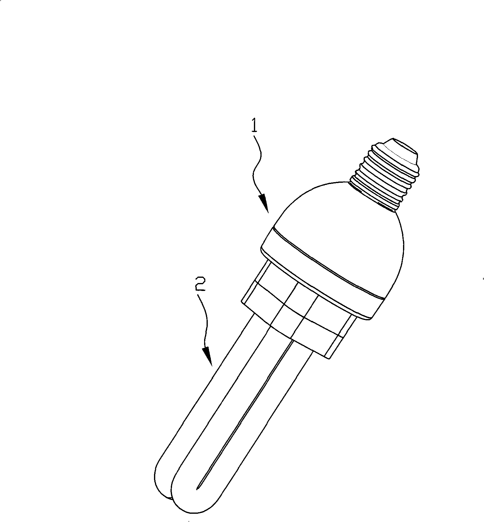
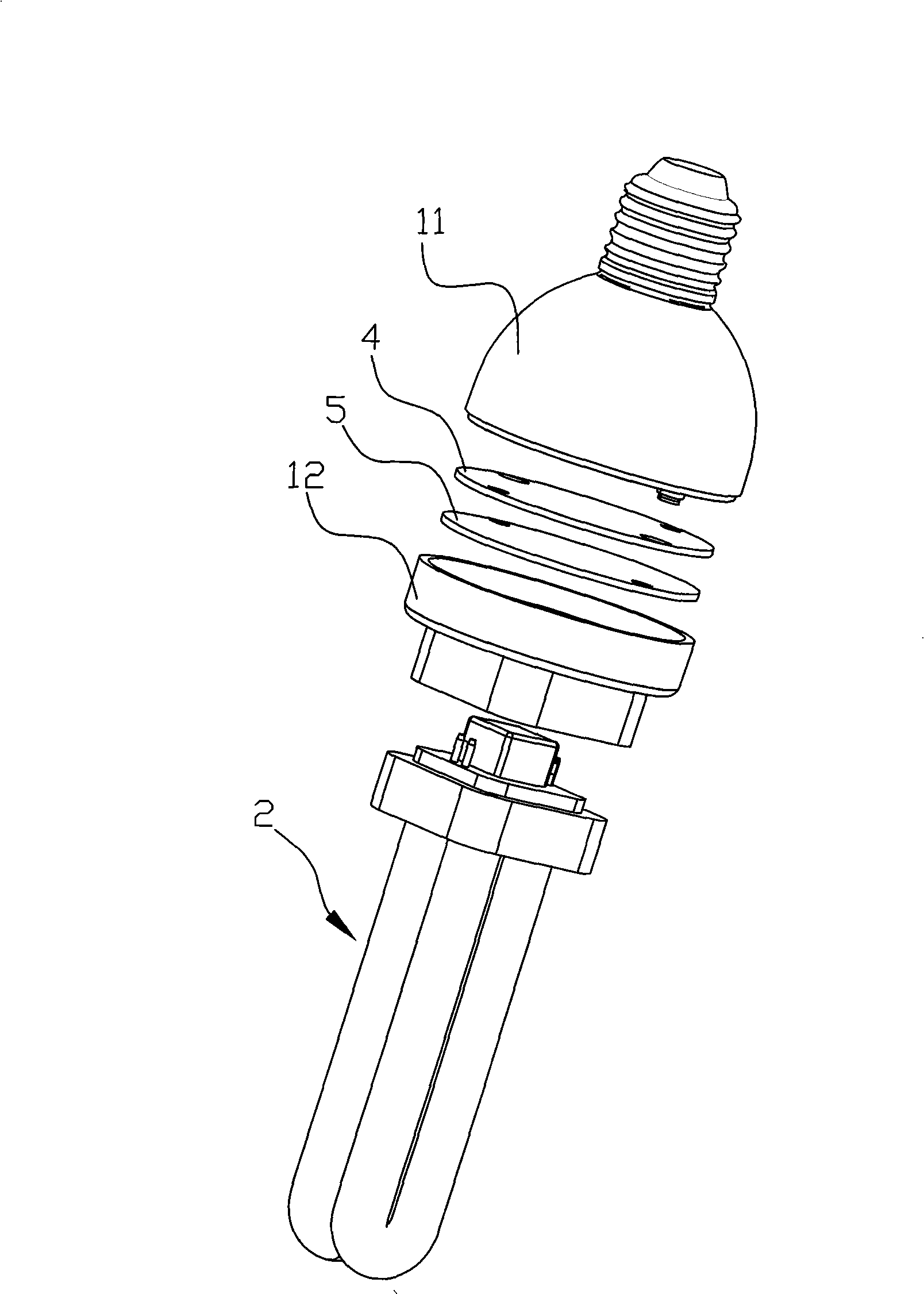
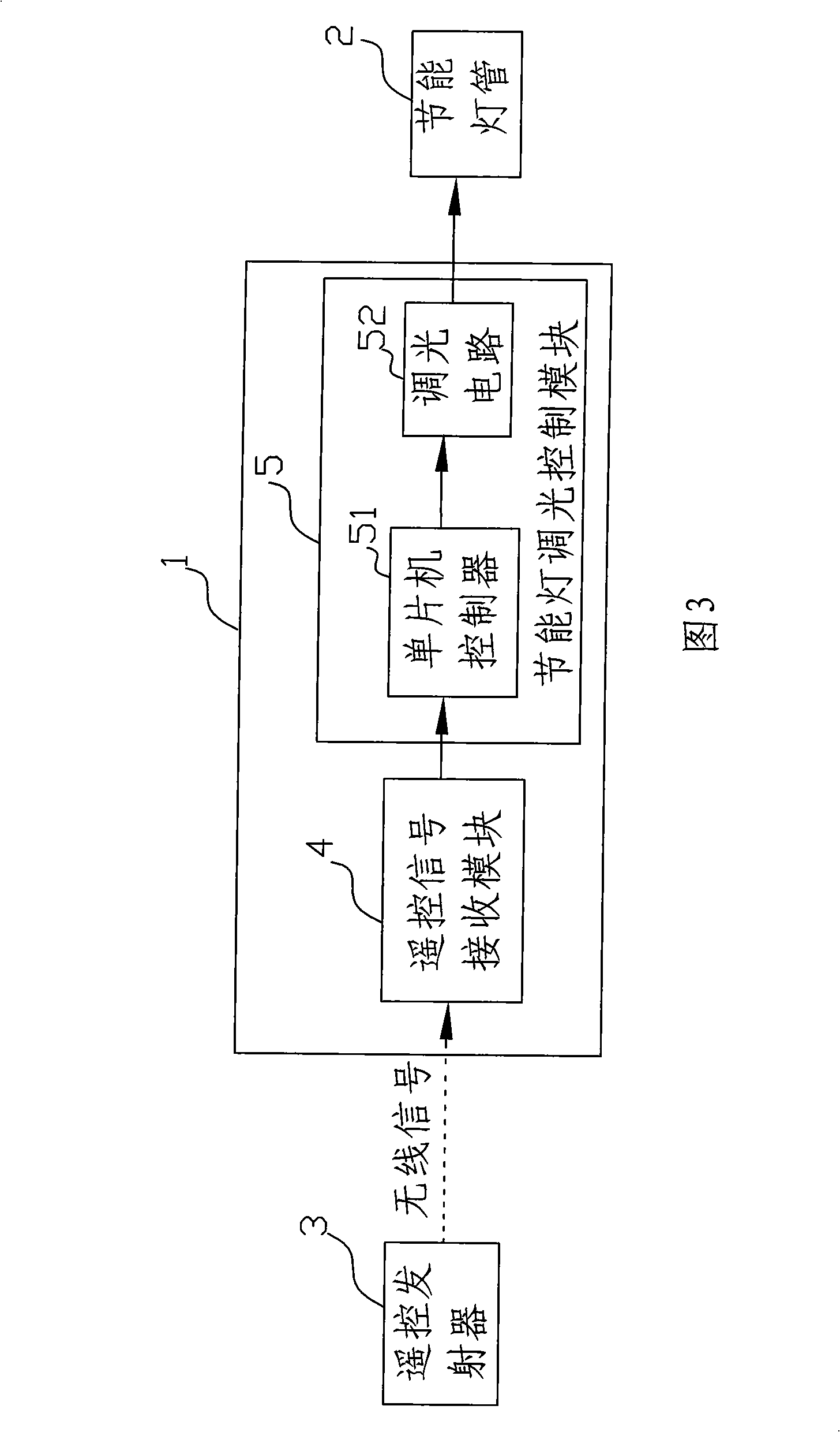
[0017] Such as figure 1 The remote dimming energy-saving lamp shown in ~3 includes an energy-saving lamp housing 1 composed of a lamp cap assembly 11 and a lamp cap 12, an energy-saving lamp tube 2, a remote control transmitter 3, a remote control signal receiving module 4 and an energy-saving lamp dimming control module 5 is located in the shell of the energy-saving lamp, and the signal output end of the remote control signal receiving module 4 is connected to the signal input end of the energy-saving lamp dimming control module 5, and the signal output end of the energy-saving lamp dimming control module 5 is connected to the signal input of the energy-saving lamp tube 2 end connected. The energy-saving lamp dimming control module 5 includes a single-chip controller 51 and a dimming circuit 52, the signal output end of the remote control si...


PUM


Abstract

The invention relates to a remote control dimmable energy-saving lamp which comprises an energy saving lamp casing (1), an energy saving lighting tube (2), a remote control emitter (3), a remote control signal receiving module (4) and an energy saving dimming control module (5); wherein, the remote control signal receiving module (4) and the energy saving dimming control module (5) are arranged in the energy saving lamp casing. The remote control dimmable energy-saving lamp is characterized in that the energy saving dimming control module (5) comprises a singlechip controller (51) and a dimming circuit (52); a signal output end of the remote control signal receiving module (4) is connected with a signal input end of the singlechip controller (51); the singlechip controller (51) outputs pulse modulation signals with different widths according to the received remote control signals, and the pulse modulation signals are connected with the signal input end of the dimming circuit (52) from the single output end of the singlechip controller (51); the dimming circuit (52) outputs different working voltages according to the received pulse modulation signals with different widths; and the working voltages are connected with the signal input end of the energy saving lighting tube (2) from the signal output end of the dimming circuit (52). Compared with the prior art, the remote control dimmable energy-saving lamp has the advantages that the energy saving lighting tube has stable lighting adjustment and large dimming range.

Description

technical field [0001] The invention relates to a remote control dimming energy-saving lamp. Background technique [0002] The Chinese utility model patent with publication number CN 200952693Y (patent number ZL 200620107961.3) discloses a "compact remote control dimming energy-saving lamp", which assembles a remote control circuit According to one's own needs, the lighting brightness of the energy-saving lamp can be remotely controlled. The technical solution is as follows: it includes the energy-saving lamp housing, the remote control circuit board, the energy-saving lamp tube and the remote control. The remote control circuit board is located in the energy-saving lamp housing and the remote control circuit board signal The output terminal is connected to the signal input terminal of the energy-saving lamp tube. However, the above-mentioned patent does not introduce how the remote control circuit board realizes remote dimming, and the light emission adjustment of the lamp...

Claims


Application Information

Patent Timeline
IPC IPC(8): H05B41/38G08C17/02G05F1/46
Inventor 秦兵许光明龙惠冬唐小武杜宝平文磊
Owner CHANGXING POTEK ELECTRONICS & TECH CO LTD
Learn More