Red luminous material for LED and producing process thereof

A red luminous, deep red technology, applied in the field of luminescent materials, can solve the problems of narrow emission peaks and limited applications, and achieve the effects of low equipment requirements, low raw material costs, and simple operation steps

Inactive Publication Date: 2009-04-08
SOUTH CHINA UNIV OF TECH
View PDF0 Cites 14 Cited by
  • Summary
  • Abstract
  • Description
  • Claims
  • Application Information

AI Technical Summary

Problems solved by technology

[0003] Traditional Eu 3+ Activated red phosphor is widely used in various lighting and displays due to its high efficiency and high color purity, but Eu 3+ The luminescence of ions is caused by their f-f transition, so the excitation peaks are narrow emission peaks in the near ultraviolet and blue light regions, which limits their application in current white LEDs (Phosphor Handbook, C

Method used


Image

  • Red luminous material for LED and producing process thereof

Examples


example 1

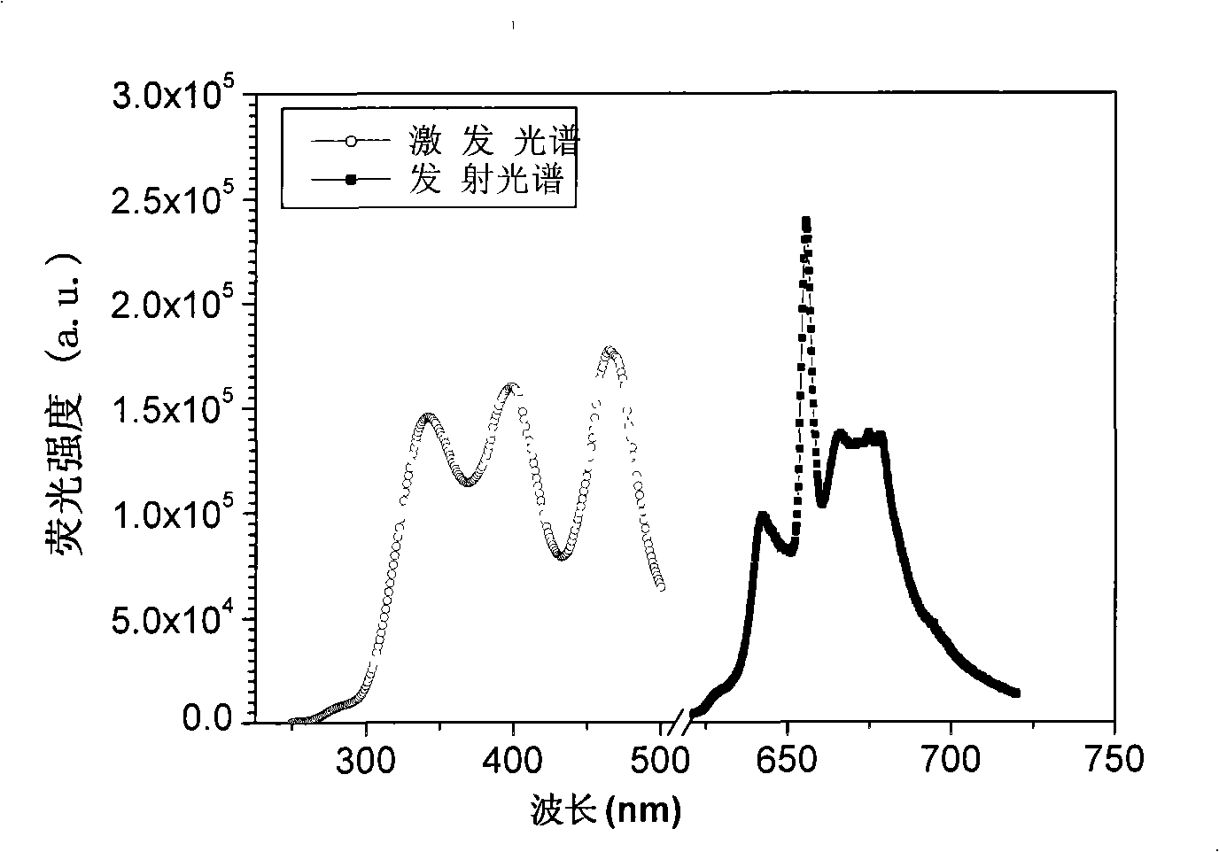
[0018] According to target product Ca 1-x-y Sr x Mg y Al 12-z o 19 :Mn 4+ (wherein x=0, y=0, z=0.01%) each ion stoichiometric ratio, accurately measure the above Ca(Ac) 2 , Al(NO 3 ) 3 , Mn(Ac) 2 After mixing the solution evenly, add urea whose molar mass is 3 times the total molar amount of metal ions, stir to dissolve it, and form a transparent viscous solution, place it on an electric furnace, heat and concentrate until it burns, and obtain a yellow precursor powder. After pre-burning in the air at 500°C for 5 hours, grind it, then sinter in the air at 1300°C for 5 hours, and cool it down to room temperature naturally to get the product. Fluorescent red.

example 2

[0020] According to target product Ca 1-x-y Sr x Mg y Al 12-z o 19 :Mn 4+ (wherein x=0.5, y=0, z=0.1%) each ion stoichiometric ratio, accurately measure the above Ca(Ac) 2 , Sr(NO 3 ) 3 , Al(NO 3 ) 3 , Mn(Ac) 2 After mixing the solution evenly, add citric acid whose molar amount is 3 times the total molar amount of metal ions, stir to dissolve it, form a transparent viscous solution, place it on an electric furnace, heat and concentrate until it burns, and obtain a brown precursor powder. The product is pre-fired in the air at 600°C for 8 hours, then ground, then sintered in the air at 1100°C for 24 hours, and cooled to room temperature naturally to obtain the product. The product emits light under the irradiation of ultraviolet lamp, ultraviolet LED or blue light LED Crimson fluorescent.

example 3

[0022] According to target product Ca 1-x-y Sr x Mg y Al 12-z o 19 :Mn 4+ (wherein x=0, y=0.5, z=0.05%) each ion stoichiometric ratio, accurately measure the above Ca(Ac) 2 , Mg(NO 3 ) 3 , Al(NO3 ) 3 , Mn(Ac) 2 Solution, after mixing evenly, add citric acid and urea with a molar mass of 1.5 times the total molar amount of metal ions, stir to dissolve, form a transparent viscous solution, place it on an electric furnace, heat and concentrate until it burns, and obtain a brown precursor powder , pre-burn the precursor in the air at 500°C for 5 hours, grind it, and then sinter it in the air at 1100°C for 18 hours, and cool it to room temperature naturally to get the product. The product is irradiated by ultraviolet lamp, ultraviolet LED or blue LED Underneath, it fluoresces dark red.


PUM


Abstract

The invention discloses a red luminescent material used for an LED and a preparation method thereof. The chemical formula thereof is Ca1-x-ySrxMgyAl12-zO19:Mn<4+>z; wherein, x is equal to or larger than 0 and less than 0.5; y is equal to or larger than 0 and less than 1; z is equal to 0.01 to 10 percent; the preparation method is as follows: materials like soluble metal acetate and nitrate are dissolved in water and uniformly mixed according to a stoichiometric ratio and are respectively added with one or a plurality of fuels like carbamide, citric acid, boric acid and glycin for forming a transparent viscous liquid; then the transparent viscous liquid is heated and condensed to be dry for obtaining a yellow or brown powder precursor. The precursor sintered in the air of 500 to 900 DEG C for 5 to 12 hours is cooled and ground and then sintered for 5 to 24 hours in the air of 1100 to 1300 DEG C and then is naturally cooled to the room temperature, thus obtaining the product. The material is used for a white light LED; and the preparation method is 200 to 400 DEG C lower than the traditional synthetic method.

Description

technical field [0001] The invention relates to a luminescent material, in particular to a red luminescent material which can be used for LED and a preparation method thereof. Background technique [0002] White LEDs packaged by yellow phosphor YAG:Ce and blue LEDs are the earliest white LEDs invented, and they are also the mainstream products in the current white LEDs market. However, the color rendering index of such white LEDs is low and cannot meet large-scale lighting needs, because the white light has only yellow and blue components, and less red components. In order to improve the color rendering index of this type of white LEDs, a lot of work has focused on using Gd 3+ Partial replacement of Y in YAG:Ce 3+ Redshift its emission spectrum to increase its emission intensity in the red light region, but this redshift of the emission band needs to be at the expense of luminous intensity and luminous efficiency (J.Electrochem.Soc.2007, 154, J326; Mater . Res. Bull. 2008...

Claims


Application Information

Patent Timeline
IPC IPC(8): C09K11/64C01F7/02H01L33/00
CPCY02B20/181Y02B20/00
Inventor 潘跃晓
Owner SOUTH CHINA UNIV OF TECH
Why Eureka
Try Eureka