
Multi-mode co-focusing imaging method and apparatus

An imaging method, confocal technology, applied in the field of optical imaging

Inactive Publication Date: 2012-07-25
上海奥通激光技术有限公司
View PDF0 Cites 0 Cited by
  • Summary
  • Abstract
  • Description
  • Claims
  • Application Information

AI Technical Summary

Problems solved by technology

None of the existing prior art can achieve the above purpose

Method used


Image

  • Multi-mode co-focusing imaging method and apparatus
  • Multi-mode co-focusing imaging method and apparatus

Examples


Embodiment Construction

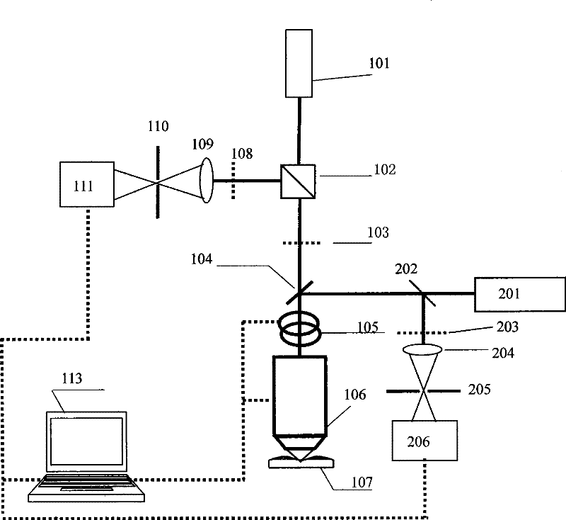
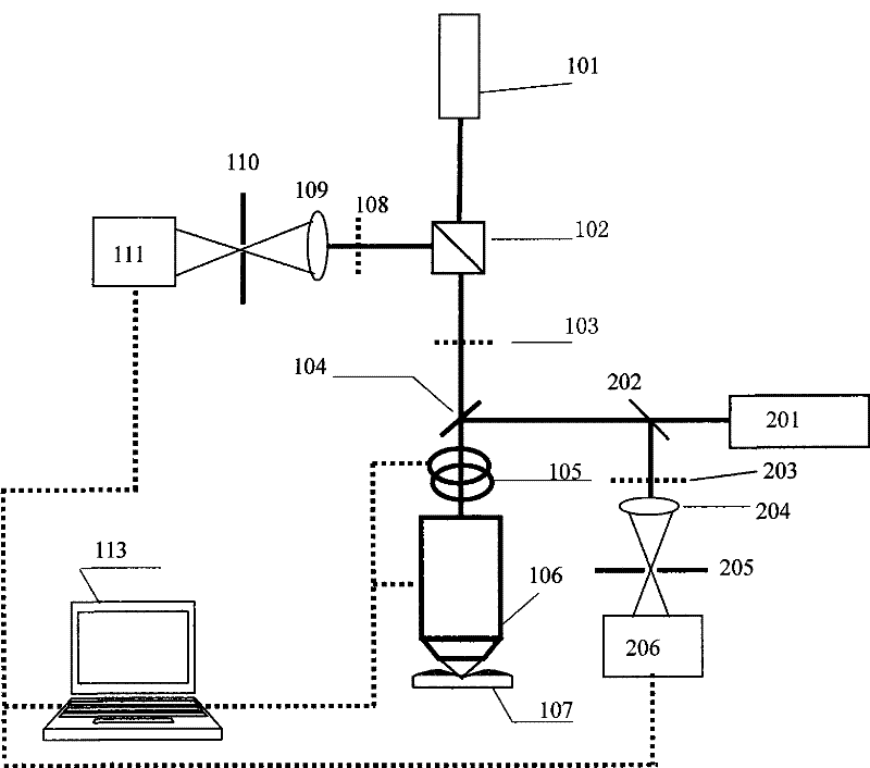
[0039] attached figure 1 A multi-mode confocal imaging device is shown, the device includes a reflection signal acquisition device and a fluorescence signal acquisition device,

[0040] Wherein the reflective signal acquisition device comprises a first laser light source 101, a prism polarizer 102, a quarter wave plate 103, a first dichroic beam splitter 104, a scanning mirror 105 and an objective lens 106 arranged sequentially along the optical path, starting from the prism A first filter 108, a first lens 109, a first confocal pinhole 110, and a first photodetector 111 are sequentially arranged on the reflection optical path of the optical path returned by the objective lens 106 of the polarizer 102, and the first photodetector 111 Connect with imaging computer system 113;

[0041] Simultaneously, the device is also provided with a fluorescence signal acquisition device, and the fluorescence signal acquisition device and the reflection signal acquisition device share the ab...


PUM


Abstract

The invention discloses a multi-mode confocal imaging method and a device thereof. The method comprises the following steps: transmitted light sources of two signal acquiring devices are combined by dichroic beamsplitters and projected onto a target tissue; reelected signal light of the target tissue is separated by the dichroic beamsplitters into two beams which reach respective filter elements to filter interference signals and then reach respective detection elements to perform synchronous imaging process to the detection signals of a sample. The device comprises a reflected signal acquiring device, a fluorescence signal acquiring device, an optical path of the two devices for light combination consisting of a first dichroic beamsplitter, a scanning mirror and an object lens, and a detection light path of the reflected signal acquiring device and a detection light path of the fluorescence signal acquiring device, wherein each detection light path comprises a filter plate, a lens, aconfocal pinhole and a photoelectric detector. The photoelectric detectors are connected with an imaging computer system. Two confocal acquisition systems acquire a signal at the same time and position, and an optical design is adopted to avoid mutual interference of multi-path laser light and the detection systems, thereby realizing real-time noninvasive 3D detection of biological tissue.

Description

technical field [0001] The present invention relates to a method for optical imaging, in particular to a method for performing multi-mode confocal optical imaging using reflection and fluorescence, which is mainly suitable for multi-mode confocal imaging of biological tissues; [0002] The invention also relates to an optical imaging device, in particular to a multi-mode confocal optical imaging device using reflection and fluorescence. Background technique [0003] The confocal reflective imaging device proposed in the prior art [1] (see Opt. Photonics News, P. Daucatas, 18, 2007, pp. 28-33) utilizes reflected light from tissues to perform imaging. Since the reflected signal is only sensitive to the refractive index, selective imaging of specific biomolecules cannot be achieved. [0004] Described in the prior art [2] (see J. Microsc., A. L. Carlson et al., 228, 2007, pp. 11-24) is a confocal reflection and fluorescence dual-mode imaging method. The basic principle is to ...

Claims


Application Information

Patent Timeline
Patent Type & Authority Patents(China)
IPC IPC(8): A61B5/00G02B21/00
Inventor 席鹏任秋实黄欣明万俊超
Owner 上海奥通激光技术有限公司
Learn More